Creates a detail view of a portion of a model documentation drawing view.
A detail view is a drawing view that contains a portion of another drawing view and is magnified to a larger scale. You can have a circular or rectangular detail view. This command is only supported in the layout and you must have a drawing view.
The following prompts are displayed.
Select parent view
Specifies a view from which to derive the detail view.
Center point
Specifies the center point on the parent for the detail view boundary.
- Size of boundary
- Specifies the size of the detail view boundary. You can specify a point or enter a polar coordinate.
- Rectangular/Circular
- Specifies the shape of the detail boundary.
- Undo
- Removes the in-progress boundary.
- Location of detail view
- Specifies where to place the detail view.
Representation
This panel is visible only when you have created a detail view from an Inventor model. When creating detail views, you can only edit the values for Design View.
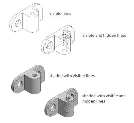
Hidden lines
Specifies the display options for the detail view.
- Visible lines
- Displays the detail view in wireframe with only visible lines showing.
- Visible and hidden lines
- Displays the detail view in wireframe with both the visible and hidden lines showing.
- Shaded with visible lines
- Displays the detail view as shaded, with only visible lines showing.
- Shaded with visible and hidden lines
- Displays the detail view as shaded, with both visible and hidden lines showing.
- From parent
- Displays the detail view with the property has inherited from the parent view.
Scale
Specifies the scale of the detail view. By default, the scale of detail view is twice of the parent view or the next larger value in the Scale list on the Appearance panel on the ribbon.
- Enter scale
- Enter the scale for the detail view.
- From parent
- Specify the same scale as the parent view.
Visibility
Specifies the visibility options to set for the detail view. Object visibility options are model specific and some options may not be available in the selected model, and in the view created of the model.
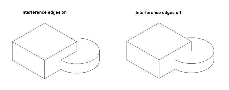
- Interference edges
-
Turns visibility of interference edges on or off. Interference edges occur when one or more solid bodies intersect with each other. When the visibility of Interference Edges is turned on, the program draws a line where the solid bodies meet.
- Tangent edges
-
Turns visibility of tangent edges on or off. Tangent edges mark the transition between a flat surface and a rounded edge, most commonly seen as filleted edges.
- Tangent edges foreshortened. Shortens the length of tangential edges to differentiate them from visible edges. This is available only if Tangent Edges is selected.

- Bend extents
-
Turns visibility of sheet metal bend extent lines on or off. Sheet metal bend extent lines indicate the location of transition about which a bend hinges or folds, in a flattened sheet metal view.
This option is available only if the corresponding model has a flattened sheet metal view defined in it.
- Thread features
-
Turns visibility of thread lines on screws and tapped holes on or off.
- Presentation trails
-
Turns visibility of presentation trails on or off. Presentation trails are lines in an exploded view (in a presentation file) that show the direction along which a components are moved into assembled position.
Boundary
Specifies the detail view boundary type.
- Circular
- Specifies that a circular boundary is used to create the detail view. This is the default boundary type.
If Infer Constraint is on, the center of the circular detail boundary is associated to a point on the parent view. If Infer Constraint is off, the center of the circular detail boundary is not associated to a point on the parent view.
- Rectangular
- Specifies that a rectangular boundary is used to create the detail view.
If Infer Constraint is on, the corner of the rectangular detail boundary is associated to a point on the parent view. If Infer Constraint is off, the corner of the rectangular detail boundary will not be associated to a point on the parent view.
Annotation
- Identifier
- Specifies the label for the detail boundary and the resulting detail view.
The program always determines from the drawing, the next free detail label.
- Label
-
Specifies if the detail view label text is displayed or not.
Model Edge
- Smooth
- Specifies that the cutout line on the model within the detail view is smooth.
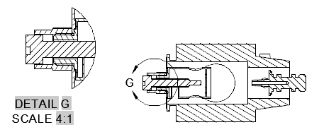
- Smooth with border
- Specifies that the cutout line on the model within the detail view is smooth and a border is drawn around the detail view.
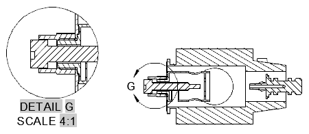
- Smooth with connection line
- Specifies that the cutout line on the model within the detail view is smooth, a border is drawn around the detail view, and leader connects the detail view to the detail boundary in the parent view.
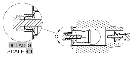
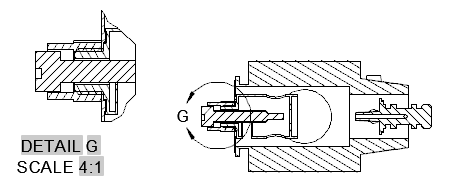
- Jagged
- Specifies that the cutout line on the model within the detail view is jagged.
There is no border for the detail view and no leader line between the detail view and the detail boundary in the parent view.
Annotation Panel
- Identifier
-
Specifies the label for the detail boundary and the resulting detail view.
- Show view label
-
Specifies if the detail view label text is displayed.
Move
Moves the detail view, after it is placed in the drawing area, without forcing you exit the command.
Exit
Goes back to the previous prompt, or completes the command, depending on where in the command cycle the option appears.