In this exercise, you will extrude the part profiles to create the 3D model. You will then establish the model parameters to control the sizing and dimensions of the manhole.
This exercise continues from Exercise 2: Defining the Manhole Geometry.
- Right-click Modifiers
 Add Path. When prompted for path, select the top line segment (the segment dimensioned LenA1), then select the Frame Cylinder Diameter profile (the circle dimensioned BdyD2) for the start profile, and select it again for the end profile. The Frame Cylinder Diameter profile is applied along the path (length) of the top line segment.
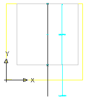
- Change the view to SE Isometric to get a better view of the Path. Change the view back to Right.
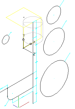
- Repeat the Add Path command for the cone segment. For the start profile, select the Cone Top Diameter profile (dimensioned with BdyD3). For the end profile, select the Barrel Cylinder Diameter profile (dimensioned with BdyD4).
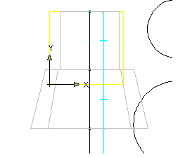
- Repeat the Add Path command for the remaining three line segments. Use the Barrel Cylinder Diameter profile for both the start and end profiles for each of the three segments. Change your view to SE Isometric to see the part in 3D. Change view back to Right.
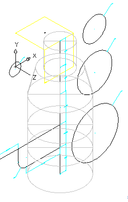
- Next, you’ll add paths for the drop pipe assembly. Right-click Modifiers
 Add Path. Select the lower horizontal segment for the path and the Drop Pipe Diameter profile for the start and end profiles.
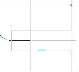
- Add Path for the curved elbow. When the Enter Number of Path Segments dialog box is displayed, verify that “Do not segment path” is checked, and then click OK. Then add the path modifier for the vertical segment of the drop pipe. Use the Drop Pipe Diameter profile.
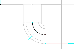
- Finish the drop pipe assembly by adding paths for the upper segments. Start with the right upper segment. Switch to SE isometric view.
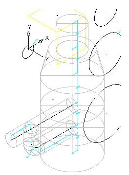
- Switch back to Right view.
Next, you will merge the structure components with the drop pipe assembly components. Right-click Modifiers
 Boolean Add. When prompted to select objects, select the bottom two barrel segments, and the lower horizontal pipe segment, and then press Enter. The parts are merged.
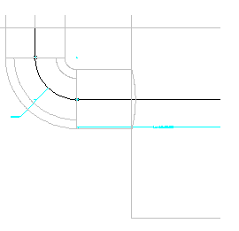
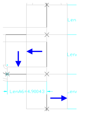
- Right-click Modifiers
 Boolean Add. When prompted to select objects, select the top two barrel segments, and the upper two horizontal pipe segments, and then press Enter.
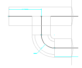
- Right-click Modifiers
 Boolean Add. When prompted to select objects, select the upper horizontal pipe segment, and the vertical pipe segment, and then press Enter.
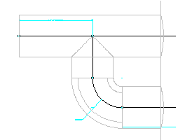
- Switch the view to SE Isometric.
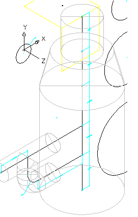
- Next you will set the placement point for the part.
Add new Top workplane; Add Point reference; Select placement point on Top workplane Expand AutoLayout Data. Right-click Layout Data, and then click Set Placement Point. Use the node object snap to click the top point on the vertical axis. This is the point at which the part is inserted into the drawing (insertion point).
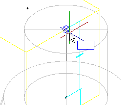
- Save the part. Click Save Part Family.
- Right-click Size Parameters
 Add
Add Edit Configuration.
 - Click New. Add the following Parameters clicking New for each:
- Barrel Height
- Frame Height (SFH)
- Frame Diameter (SFD)
- Cone Height (SCH)
- Inner Structure Diameter (SID)
- Barrel Pipe Clearance (SBPC)
Click OK when all of the parameters have been added.
- Click Save Part Family. Right-click Model Parameters, and then click Edit. Double-click in the Equation column next to each of the following, and set the Equation for each parameters as shown below:
- FTh to 6
- WTh to 4
- SBH to 74
- FTh to 6
- SBPC to 3
- SBSD to 48
- SBSH to 108
- SCH to 24
- SFD to 24
- SFH to 4
- SID to 48
- SRS to 102
- SVPC to 36
- WTh to 4
Saving the part causes the Model Parameters to update, including the new Size Parameters.
- Right-click Size Parameters, and then click Edit Configuration. The Edit Part Size dialog box is displayed.
- Locate the SRS column, click Constant, and change it to Range. The SRS parameter is now formatted as a range of values. Click the drop-down arrow button next to Parameter Configuration, and select Values. The view is changed to show the value of each parameter. Click the cell in the SRS column, and then click the Edit button on the Edit Part Sizes dialog box toolbar. The Edit Values dialog box is displayed. Set the Minimum to 36, the Maximum to 12000, the Default to 120, and then click OK.
- Right-click Model Parameters, and then click Edit. Edit the Equations and Descriptions for the BdyD# parameters as shown in the following table:
BdyD1 12 Elbow Bend Diameter BdyD2 SFD Frame Cylinder Diameter BdyD3 SFD+(2*Wth) Cone Top Diameter BdyD4 SID+(2*Wth) Barrel Cylinder Diameter BdyD5 12 Incoming Pipe Diameter - Make the following additional edits:
SBH SRS-SFH-SCH SBPC 3.0 SBSD SID+(2*Wth) SBSH SRS+FTh - Edit the Equations and Descriptions for the LenA# parameters as shown in the following table:
LenA1 SFH Frame Cylinder Height LenA2 SCH Cone Cylinder Height LenA3 SVPC-SFH-SCH+(BdyD5/2) Top Pipe CL LenA4 SRS+FTh-SFH-SCH-LenA3-LenA5 Top Pipe CL to Bottom Pipe CL LenA5 24 Bottom Pipe CL to Struct Bottom LenA6 (SID/2)+WTh+(BdyD5/2+2) CL Vert Pipe to Incoming Pipe Click Close. Change to SE Isometric view and note the changes to the geometry of the structure.
- Change the 4 circular profiles so they are not visible by right-clicking on each and then clicking Visible.
The circular profiles are no longer visible.
- Repeat the previous step for all of the Dimensions.
- Change view to SE Isometric and examine the part. It should look like the following image.
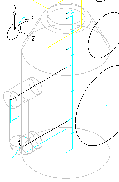
Click Save Part Family. Close out of the Part Builder Environment, and then re-open the Part.
To exit the Part Builder utility, click the small X in the upper right corner of the Part Browser. (The Part Browser is the left pane portion of the Part Builder application window.) If you are prompted to save the part, click Yes. Part Builder closes.
After all the changes that have been made, now is a good time to close out and re-open the part so that all of the data is freshly loaded into the part builder environment.
- Right-click Size Parameters, and then click Edit Configuration.
- Change the Data Storage type to List for the following parameters:
- WTh
- FTh
- SFH
- SFD
- SCH
- SID
- Click the drop-down arrow button next to Parameter Configuration, and select Values.
- Select the 4.000 in the WTh column, click the Edit button from the Edit Part Sizes dialog box toolbar, and add the following values: 4.0, 6.0. Click OK.
- Repeat the previous step for each of the following parameters:
- FTh: 6.0, 8.0, 12.0
- SFH: 4.0, 6.0, 8.0
- SFD: 24.0, 36.0
- SCH: 24.0, 36.0
- SID: 48.0, 60.0, 72.0
- Click the drop-down arrow button next to Values, and select Calculations.
- Double click in the cell in the PrtSN to open the Calculation Assistant.
- Change the Precision to 0.
- Click in the text box, right after PrtD, and press the space bar.
- From the Insert Variable list, select FTh and then click Insert. The FTh variable is inserted into the Part size name.
- Enter “in Floor” after the FTh variable. (Exclude the quotation marks.)
- Repeat the previous steps, adding variables and text for SCH, SFD, SFH, SID, WTh. The complete string should look something like this:
PrtD FTh in Floor SCH in Cone Hgt SFD in Frame Dia SFH in Frame Hgt SID in Barrel Dia WTh in Wall.
- Click Evaluate to see the resultant part name.
Note that the name is long and partially cut off on the right. Click the name and use your keyboard arrow keys to see the rest of the name. This is a required step to ensure that each part has a unique part name when added to the part list.
- Click OK twice to close all dialog boxes.
- Save the Part. Switch Visual Style to Conceptual. The part should look like the following:
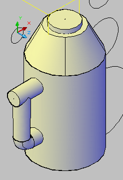
- Right-click Model Parameters, and then click Edit.
- Double click the Equation for SVPC and enter: SFH+SCH+SBPC. Change the Visual Style to 2D Wireframe. Right-click Vertical Axis
 Add Geometry
 Point Reference.
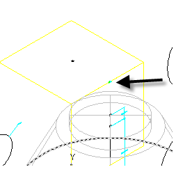
 - Click the point in the center of the Rim work plane.
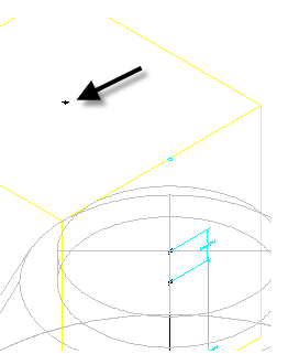
A reference point (green) is created where the two planes meet in line with the vertical axis of the structure.
- Right-click Vertical Axis
 Add Constraints
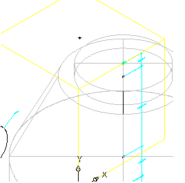
 Coincident. Click the top point of the vertical axis, then click the reference point created in the previous step. The entire structure moves upward so that the rim elevation matches the top work plane.
- Click Generate Bitmap.
- Click SE Isometric View.
- Click OK. A bitmap image is generated. This is the image of the part that is displayed when viewing the part in the part catalog. It is not used not when viewing the part in a drawing.

- Click Save Part Family.
- Exit the Part Builder utility by clicking the small X in the upper right corner of the Part Browser. (The Part Browser is the left pane portion of the Part Builder application window.) If you are prompted to save the part, click Yes. Part Builder closes.
You can open Part Builder-2.dwg in the tutorials drawings folder to see what this finished part looks like in a drawing.