In this exercise, you will create a fairly complex assembly with a depressed median and separated lanes.
Create an assembly baseline
- Open Corridor-3a.dwg, which is available in the tutorials drawings folder.
- Click tab
 panel
panel  drop-down
  Find.
Find. - In the Create Assembly dialog box, for Name, enter Divided Highway. Click OK.
- When the ‘Specify assembly baseline location’ prompt is displayed on the command line, click a point in the drawing to build the assembly.
The viewport zooms to the assembly baseline, which looks like this:

Add a median subassembly
- If the Tool Palette containing the subassemblies is not visible, click Home tab
 Palettes panel
  Tool Palettes Find.
 - In the tool palette, right-click the Tool Palettes control bar. Click Civil Imperial Subassemblies.
- Click the Medians tab.
- Right-click
 MedianDepressedShoulderExt. Click Help. Review the diagram to better understand the subassembly.
 - Click
 MedianDepressedShoulderExt.
 - In the Properties palette, under ADVANCED, specify the following parameters:
- Centerline Pivot: Pivot about centerline
- Left Median Width: 22.0000
- Right Median Width: 22.0000
- In the drawing, click the marker point on the assembly baseline. A depressed median and inside shoulders are drawn.
Add a lane subassembly
- In the drawing, pan to the left edge of the MedianDepressedShoulderExt subassembly. Zoom in so that each marker point can be seen distinctly.
- In the tool palette, click the Lanes tab.
- Click
 LaneSuperelevationAOR.
 This subassembly inserts a travel lane that follows the slope for the superelevation properties of the alignment.
Note:For more information about superelevation, see the Applying Superelevation to an Alignment tutorial.
- In the Properties palette, under ADVANCED, specify the following parameters:
- Side: Left
- Width: 24.0000
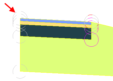
- In the drawing, click the marker that is at the top left edge of the median to insert the lane:

Add a shoulder subassembly
- In the drawing, pan to the left side of the LaneSuperelevationAOR subassembly.
- In the tool palette, click the Shoulders tab.
- Click
 ShoulderExtendSubbase.
 - In the Properties palette, under ADVANCED, specify the following parameters:
- Side: Left
- Use Superelevation Slope: Outside Shoulder Slope
- Subbase - Use Superelevation: Outside Shoulder Slope
This sets these slopes to the outside shoulder superelevation slope. For more information, see the subassembly help.
- In the drawing, click the marker point at the top outside edge-of-lane on finish grade to add the paved shoulder.
Add a daylight subassembly
- In the drawing, pan to the left side of the ShoulderExtendSubbase.
- In the tool palette, click the Daylight tab.
- Right-click
 DaylightStandard. Click Help. Review the diagram and Behavior section to better understand the cut and fill daylighting behaviors.
 - In the tool palette, click
 DaylightStandard.
 - In the drawing, click the marker point at the outside edge of the ShoulderExtendSubbase subassembly to add the daylight slopes for cut and fill.
Mirror the subassemblies to the right side of the baseline
- Press Esc to exit subassembly placement mode.
- In the drawing, zoom out until you see the entire assembly. On the left-hand side of the assembly, select the daylight, shoulder, and lane subassemblies. Right click. Click Mirror.
- Click the marker point at the top-right edge of the median subassembly to draw a mirror of the daylight, shoulder, and lane subassemblies.
The Mirror command creates a mirror image of the selected subassemblies. All the subassembly parameters, except for the Side parameter, are retained.
Note:The parameters of the mirrored subassemblies are not dynamically linked. If you change a parameter value for a subassembly on one side of the assembly baseline, the change will not be applied to the opposite side.
The finished assembly looks like this:

To continue this tutorial, go to Exercise 3: Creating a Divided Highway Corridor.