In this exercise, you will define the geometry of the manhole by creating a simple schematic of the structure profile. You will build this portion with dimensions that can be modified from within AutoCAD Civil 3D when the part is in use.
This exercise continues from Exercise 1: Defining the New Part in the Structure Catalog.
- Click View tab
 Views panel
  Front.
 The view of your Part Builder drawing area changes so that you see the Rim work plane from a front view.
- Expand Modeling. Right-click Work Planes and then click Add Work Plane. The Create Work Plane dialog box is displayed.
- Click Offset. Name the work plane Top of Riser 1 then click OK.
- The command line asks you to Select reference work plane. Click the yellow bounding square of the Rim work plane.
The command line asks you to Select Offset from work plane. Turn on ORTHO. Select a location approximately 12” lower than the Rim work plane in the negative Z direction, and press enter. In later steps, you will establish a more precise offset by equating these distances with structure parameters. A second work plane is displayed approximately 12” below the first work plane.
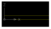
- Repeat Steps 2 through 4 to create the following additional work planes, using the following approximate offsets from the referenced work plane:
- Name: Top of Cone, Offset: 12" below 'Top of Riser 1'
- Name: Top of Riser 2, Offset: 24" below 'Top of Cone'
- Name: Top of Barrel, Offset: 85" below 'Top of Riser 2'
- Name: Bottom of Structure, Offset: 200" below 'Top of Barrel'
The new work planes are displayed. The new parameters are displayed under Model Parameters showing you the work plane offsets.
- Change your view to be oriented above the Rim work plane. Expand Work Planes, right-click Rim and then click Set View. The view is oriented to be above the Rim work plane.
- Add a circular profile to represent the diameter of the frame. Right-click the Rim work plane
 Add Profile
 Circular. At the command prompt, select a center point for the profile at the approximate center of the work plane and a radius of 12”, similar to how you would draw an AutoCAD circle. A circular profile is displayed, and an entry for a circular profile is displayed under the Rim work plane.
 - Expand Work Planes, right-click Rim
 Add Geometry
 Point. Place a point at the approximate center of your circular profile. A point is displayed at the approximate center of the circular profile.
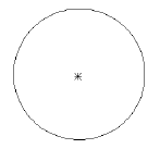
- Constrain the profile so that the point will be forced to always be located at the center of the profile. Right-click the Rim work plane
 Add Constraints
 Concentric. The command line prompts you to select a first geometry and a second geometry. Select the point and the circular profile. The point moves to be at the center of the circular profile, and a concentric constraint is displayed under the Rim work plane.
 - Add a diameter dimension that you can later use as a structure parameter. Right-click the Rim work plane
 Add Dimension
 Diameter. The command line prompts you to select circle or arc geometry. Select the circular profile on the screen. The command line prompts you to select a dimension position. Select a location on your screen that is close to the profile, but out of your way. A diameter dimension is displayed on screen as well as under your Model Parameters. The actual drawn diameter and dimension value are unimportant at this time.
 - Draw a circular profile on the Top of Riser 1 work plane. Right-click the Top of Riser 1 work plane, and then click Add Profile
 Circular. Following the same procedure as Step 7, draw a circular profile. You can use your center OSNAP to ensure that the center of this profile matches the center of the profile from the Rim work plane. Set the radius to be just slightly larger than the Rim work plane circular profile to ease selection of this profile. The actual radius is not important at this time. A circular profile is displayed.
 - Add a diameter dimension to the circular profile on the Top of Riser 1 work plane. Right-click the Top of Riser 1 work plane, and then click Add Dimension
 Diameter. Follow the same procedure as step 10 to place the dimension. A diameter dimension is displayed for your second circular profile.
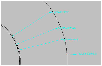
 - Repeat the previous two steps to create a circular profile and corresponding dimension on the Top of Cone work plane. You have three circular profiles with appropriate dimensions. Your dimensions may look different than the following illustration.
- Repeat steps 11 and 12 to create a circular profile and corresponding dimension for the Top of Riser 2 work plane; however, this time, make the profile radius approximately twice as large (approximately 24” radius/48” diameter). You should have four circular profiles displayed, and four corresponding dimensions displayed in the modeling area, and under Model Parameters node.
- Click View tab
 Views panel
  Front. Four profiles from front view are displayed.
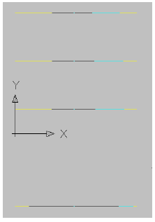
- Add a transition between the Rim circular profile and the Top of Riser 1 circular profile. This represents the manhole cover and frame. Right-click Modifiers and then click Add Transition. The command line prompts you to Select Start Profile. On the screen, select the circular profile on the Rim work plane. The command line prompts you to Select End Profile. On the screen, select the circular profile on the Top of Riser 1 work plane. A transition is displayed similar to the following illustration:
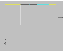
- Right-click the transition on the screen, and then click Display Order
 Send to Back. Add a transition between the Top of Riser 1 circular profile and the Top of Cone circular profile. This represents the manhole cover and frame. Right-click Modifiers and then click Add Transition. The command line prompts you to Select Start Profile. On the screen, select the circular profile on the Top of Riser 1 work plane. The command line prompts you to Select End Profile. On the screen, select the circular profile on the Top of Cone work plane.
 Repeat the process to create a transition between the circular profiles on the Top of Cone work plane and the Top of Riser 2 work plane. Remember that you may have to use Display Order
 Send to Back to send the transitions to the back, so that you can choose the profiles. To do this, right-click the transition on the screen, and then click Display Order
 Send to Back. Transitions are displayed similar to the following illustration:
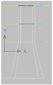
These transitions stay dynamic to profiles used to create them, including adjustments to work plane offsets, and diameter dimensions.
- Switch your view back to an overhead view by selecting the Top of Barrel work plane, right-clicking and choosing Set View. Your view switches to an overhead view in relation to this work plane.
- Make two circular profiles with corresponding dimensions on the Top of Barrel work plane. Use steps 11 and 12 for reference. The first should be approximately the same size as the profile on the Top of Riser 2 work plane (24”R/48”D), the second should be approximately twice as large (48”R/ 96”D). Two circular profiles are displayed on your screen. Two corresponding dimensions are displayed both on screen and under Model Parameters.
- Make one circular profile with a corresponding dimension on the Bottom of Structure work plane. Use steps 11 and 12 for reference. The profile should be approximately the same size as the larger profile on the Top of Barrel work plane (48”R/ 96”D). You should now have seven (7) total circular profiles and corresponding dimensions both on screen and under Model Parameters. Remember that these diameters are approximate at this point. The ones you created may not look exactly like the ones displayed in this tutorial.
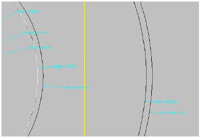
- Change your view to a Front view. The stack of work planes and the transitions created in step 17 are displayed.
- Following the same methodology for the first batch of transitions created in steps 16 and 17, add transitions between the Top of Riser 2 Profile, and the smaller Top of Barrel profile, then the larger Top of Barrel profile and the Bottom of Structure profile. (You may have to use Draw Order to send certain profiles to the back, in order to choose the correct one for each transition.) The model you created should now look similar to the following illustration:

- Change your view to SW isometric.
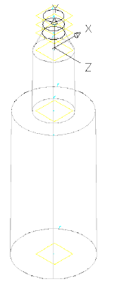
- Change your visual style to Conceptual.
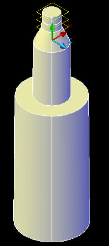
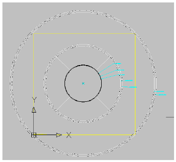
- Change your visual style back to 2D wireframe, then change your view back to Top view.
To continue this tutorial, go to Exercise 3: Matching Offsets and Dimensions to Parameters.