In this exercise, you will add ConditionalCutOrFill subassemblies to an existing corridor assembly.
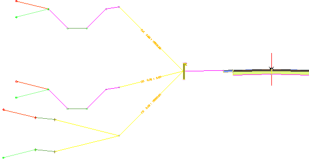
You will specify two levels of ConditionalCutOrFill subassemblies. In the first level, you will attach three ConditionalCutOrFill subassemblies to an existing guardrail subassembly, and then add standard daylight subassemblies to them:
- Cut: Add a ditch, and then daylight to surface at a 2:1 slope.
- Fill < 5.0000’: Add a ditch, and then daylight to surface at a 8:1 slope.
- Fill > 5.0000’: Add benching, and then daylight to surface at a 4.0:1 slope.
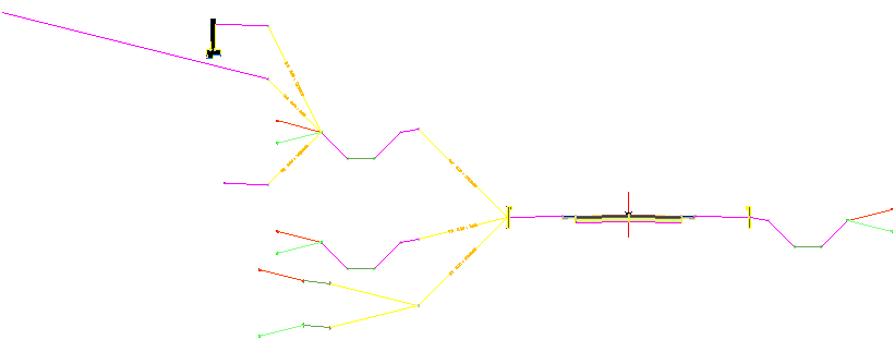
You will add a second level of ConditionalCutOrFill subassemblies to the ditch subassembly that is applied in cut conditions:
- Cut < 5.0000’: Daylight to the surface at a point that is 60’ from the baseline.
- Cut > 5.0000’: Add a 12.0’ daylight link at a -2.0% slope, and then add a retaining wall.
- Fill: Slope to surface at 4.0%.
This exercise continues from Exercise 1: Examining the Existing Corridor in Section.
Add three conditional subassemblies
- If the Tool Palette containing the subassemblies is not visible, click Home tab
 Palettes panel
  Tool Palettes Find.
 - In the tool palette, right-click the Tool Palettes control bar. Click Civil Imperial Subassemblies.
- Click the Conditional tab.
- Click
 ConditionalCutOrFill.
 - In the Properties palette, specify the following parameters:
- Side: Left
- Layout Width: 20.0000’
- Layout Grade: 4.000:1
- Type: Fill
- Minimum Distance: 0.0000’
- Maximum Distance: 5.0000’
Note:The Layout Width and Layout Grade parameters only affect the appearance of the subassembly in layout view. These parameters enable you to position the conditional subassembly and subassemblies that are attached to it, but do not affect the corridor model.
- In the drawing, in the top viewport, click the left guardrail to add the ConditionalCutOrFill subassembly.

- Add a second ConditionalCutOrFill subassembly to the left guardrail using the following parameters:
- Side: Left
- Layout Width: 20.0000’
- Layout Grade: 1.000:1
- Type: Fill
- Minimum Distance: 5.0001’
- Maximum Distance: 10000.0000’
- Add a third ConditionalCutOrFill subassembly to the left guardrail using the following parameters:
- Side: Left
- Layout Width: 20.0000’
- Layout Grade: 1.000:1
- Type: Cut
- Minimum Distance: 0.0000’
- Maximum Distance: 10000.0000’
Add a daylight bench subassembly
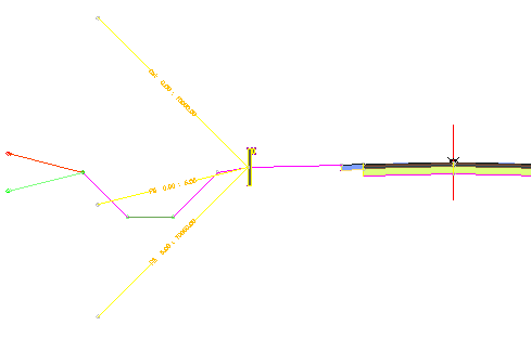
- Using the Daylight tool palette, add a
 DaylightBench subassembly to the Fill 5.00 : 10000.00 conditional subassembly using the following parameters:
 - Side: Left
- Cut Slope: 4.000:1
- Max Cut Height: 5.0000’
- Fill Slope: 4.000:1
- Max Fill Height: 5.0000’
- Bench Width: 6.0000’
- Bench Slope: -10.000%
- Press Esc to exit subassembly placement mode.
Move and copy the original daylight subassembly
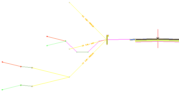
- Select the original left ditch subassembly. Right-click. Click Move To. Click the Fill 0.00 : 5.00 conditional subassembly.
- Select the ditch subassembly that you just moved. Right-click. Click Copy To. Click the Cut 0.00 : 10000.00 conditional subassembly.
When you are finished, the assembly should look like this:

Add a second level of conditional subassemblies
- Using the Conditional tool palette, add a
 ConditionalCutOrFill subassembly to the hinge point on the daylight basin subassembly for the cut condition using the following parameters:
 - Side: Left
- Layout Width: 12.0000’
- Layout Grade: 0.500:1
- Type: Cut
- Minimum Distance: 5.0001’
- Maximum Distance: 10000.0000’
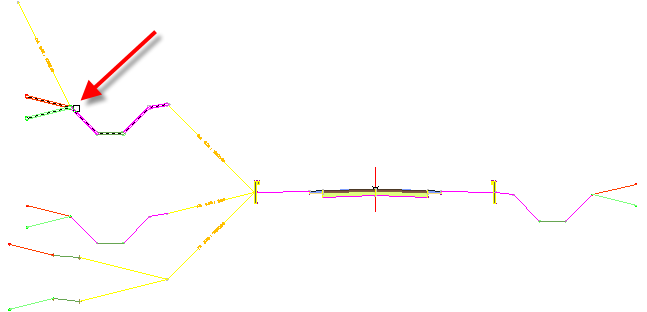
- Add a second ConditionalCutOrFill subassembly to the hinge point on the daylight basin subassembly using the following parameters:
- Side: Left
- Layout Width: 12.0000’
- Layout Grade: 1.000:1
- Type: Cut
- Minimum Distance: 0.0000’
- Maximum Distance: 5.0000’
- Add a third ConditionalCutOrFill subassembly to the hinge point on the daylight basin subassembly using the following parameters:
- Side: Left
- Layout Width: 12.0000’
- Layout Grade: 1.000:1
- Type: Fill
- Minimum Distance: 0.0000’
- Maximum Distance: 10000.0000’
Add subassemblies to the second level
- Using the Generic tool palette, add a
 LinkWidthAndSlope subassembly to the Cut 5.00 : 10000.00 conditional subassembly using the following parameters:
 - Side: Left
- Width: 12.0000’
- Slope: -2.000%
- Using the Retaining Walls tool palette, add a
 RetainWallVertical subassembly to the LinkWidthAndSlope subassembly using the default parameters.
 - Using the Generic tool palette, add a
 LinkOffsetOnSurface subassembly to the Cut 0.00 : 5.00 conditional subassembly using the following parameters:
 - Offset From Baseline: -60.000’
- Omit Link: No
- Using the Generic tool palette, add a
 LinkSlopeToSurface subassembly to the Fill 0.00 : 10000.00 conditional subassembly using the following parameters:
 - Side: Left
- Slope: 4.000%
- Add Link In: Fill Only
Note:The Fill 0.00 : 10000.00 conditional subassembly that is attached to the cut branch of the assembly will be applied if the daylight basin subassembly were to end in a fill condition.
- Press Esc to exit subassembly placement mode.
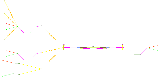
When you are finished, the assembly should look like this:

To continue this tutorial, go to Exercise 3: Adjusting Conditional Subassembly Properties.