In this exercise, you will learn some ways to view drawing objects in three-dimensional views.
This exercise continues from Exercise 2: Changing the Display of an Object.
Examine object display in model views
- Click the left viewport to make it active.
- Click View tab
 Views panel
  views list
  SE Isometric.
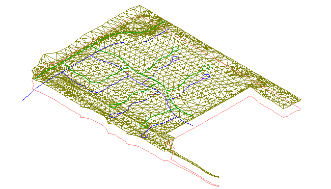
 A Southeast isometric view of the surface is displayed in the left viewport, and the right viewport stays in plan view.
- Zoom in to the isometric view of the surface.
Notice the green and blue lines. The green lines are the layout profiles that you examined in profile view. They are green because the Model view direction in its style indicated that they will display as green. The blue lines under the surface are the horizontal alignments from which the profiles were created.
The SE Isometric 3D View
This tutorial uses Intro-2.dwg from the previous tutorial.
Change the visual style of the surface
- Click View tab
 Visual Styles panel
 Visual Styles drop-down
  3D Wireframe.
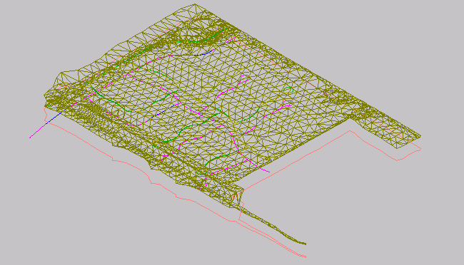
 AutoCAD visual styles give a fast, basic visualization of an object that is useful for on-screen presentation in AutoCAD Civil 3D. The 3D Wireframe visual style displays the surface in model view without applying a fill material to the object.
The 3D Wireframe visual style
Notice that a cube is displayed in the upper right-hand corner. This is the AutoCAD ViewCube, which provides visual feedback of the current orientation of a model. You can use the ViewCube to adjust the viewpoint of the model when a visual style has been applied.
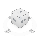
- Click a corner of the ViewCube, and drag it to a new position. Experiment with dragging the ViewCube to various positions. When you are finished, click
 to return the model and ViewCube to their original positions.
 - Click View panel
 Visual Styles panel
 Visual Styles drop-down
  Conceptual.
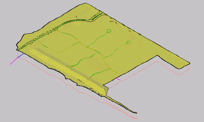
 The Conceptual visual style shades the object and smooths the edges between polygon faces. The shading in this style uses the Gooch face style, a transition between cool and warm colors rather than dark to light. The effect is not realistic, but it can make the details of the model easy to see.
The conceptual visual style
- Click View tab
 Visual Styles panel
 Visual Styles drop-down
  Realistic.
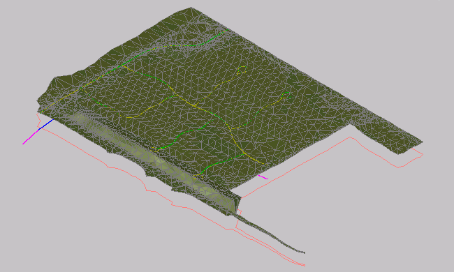
 The Realistic visual style shades the surface and smooths the edges between polygon faces. The render material that is specified in the surface style is displayed.
The realistic visual style
