This section explains the concepts and procedures for managing data shortcuts.
Using data shortcuts involves two main processes:
- Create data shortcuts from their source drawings.
- Create data references in consumer drawings to source objects in source drawings.
Data shortcuts can be used for surfaces, alignments, profiles, corridors, pipe networks, pressure networks, and view frame groups.
When you create a profile data shortcut, a data shortcut to the parent alignment is also created.
When you create a data shortcut for a corridor that uses alignments and profiles for its baselines, data shortcuts are automatically created for those baselines. If corridor baselines are comprised of feature lines, shortcuts are not created independently for those feature lines, but when the corridor shortcut is referenced into a drawing, the baselines are treated as alignments/profiles. For more information, see To Create Corridor References.
Relationship Between Shortcuts and Data References
A data shortcut provides a direct path to the location of a shareable source object. In a single operation, you can create data shortcuts for multiple objects in a source drawing. The data shortcut is used only for the creation of data references.
A data reference is a read-only copy of a source object, inserted into another drawing, often called a consumer drawing. From the Prospector tab, you can select a shortcut for an object and create a reference to that object in the active drawing. The data reference maintains an active link to the source object in the source drawing, without relying on the data shortcut.
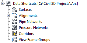
On the Toolspace Prospector tab, the Data Shortcuts node displays the path to the active project, where data shortcuts are stored. These data shortcuts can be created from any drawings associated with the active project. The figure shows how the Data Shortcuts node appears if the active project is Arc.

Shortcut folders on the Prospector tree for sample project Arc
If you change the active project, the new project name appears on the Data Shortcuts node, and the subfolders contain only the shortcuts in the new active project. A particular consumer drawing can contain data references from multiple projects.
Data Reference Attributes
The reference object has read-only geometry, but the user can apply a local object style, apply custom annotation, do limited analysis, and access the source object's properties. The reference object takes up less file space when the consumer drawing is saved. If the source object is edited, the synchronization process ensures that changes are reflected in the reference object. Synchronization occurs when the consumer drawing is opened, and can also be done manually by a user. You can promote a data reference to an independent object that can be edited; after promotion it is no longer updated from its original source object.
Persistence of Data Reference Geometry in Drawings
Persistence of Reference Geometry for Objects Except Surfaces
In AutoCAD Civil 3D 2014, the behavior of data references for object types except for surfaces was changed. When you insert a reference to a data shortcut into a drawing, and then you save and close the drawing, the object geometry is saved in the drawing. When you re-open the drawing that contains the reference, the reference is only validated and synchronized if the source object has changed.
This behavior makes it easier to share drawings which contain references with others because the referenced objects are still visible even if the source drawings are not available. And because synchronization only occurs if the source object has changed, an object in a drawing that relies on a data reference (such as a corridor which contains an alignment that is a reference) is only marked as Out Of Date when an actual change to the data has occurred.
Persistence of Reference Geometry for Surfaces
In AutoCAD Civil 3D 2017, the ability to save the geometry of reference surfaces in the drawing was added. A setting in the CreateSurfaceReference command settings is available that you can use to specify whether you want this behavior or not. If you choose to save the geometry of a reference surface in the drawing, the drawing that contains the reference will become larger, but will open more quickly unless the source surface has changed. For more information, see To Work With Surface References.