You can adjust the Interpolation and interpShape channels in the Channel Editor for each set of linked Front1 and Front2 splines to refine a morphing effect.
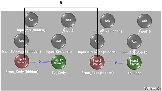
Each pair of linked Spline nodes produces an interpolated spline, which in turn, can be edited and animated independently.
(a) Interpolation and interpShape channels appear for linked spline nodes
The two interpolation channels, corresponding to linked spline nodes, are always in the Front1 source Spline node's folder in the Channel Editor.
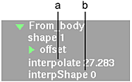
(a) Corresponds to value in Interpolation field of Warp or Morph menu (b) Contains vertex information for interpolated spline
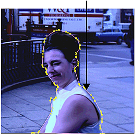 With Result selected in the View box, Front1 (Input1) selected in the Input box, and Source enabled, the source spline on Front1 (Input1) is displayed. It has a shape channel containing its vertex positions over time. .Image courtesy of Behavior Communications Inc. |
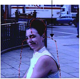 With Result selected in the View box, Front2 (Input2) selected in the Input box, and Source enabled, the source spline on Front2 (Input2) is displayed. It also has its own shape channel containing its vertex positions over time. .Image courtesy of Behavior Communications Inc. |
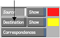
When an Front1 and Front2 spline are linked in the schematic, you select Result in the View box, Front2 in the Input box, and Destination to view the interpolated spline. The interpolated spline is the result of mixing the Front1 and Front2 source splines. Since it is the target of the morphing effect, you must click Destination to display it.
The interpolated spline's vertex information is contained in the interpShape channel in the corresponding Front1 spline's folder. Although the spline is a result of mixing the Front1 and Front2 source splines according to the Interpolation value, it can be controlled and animated independently.
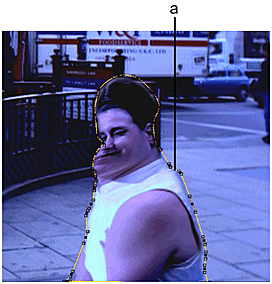
(a) Morph follows contour of interpolated spline
.Image courtesy of Behavior Communications Inc.