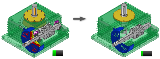
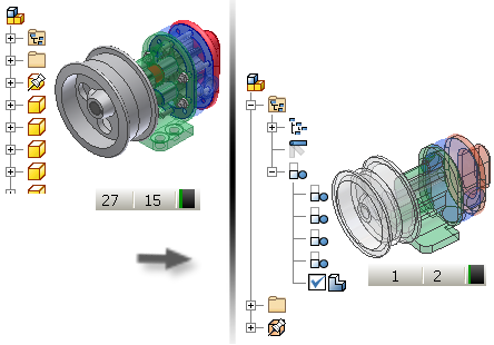
Use Level of Detail representations to specify which components are loaded in memory or to create a single part representation. You can create several representations to load different aspects of the assembly, as well as manage memory consumption.
At any time, you can change to a different Level of Detail representation. Double-click its name in the browser to activate it, or if you prefer, right-click the name and select Activate.
Examine the system-defined Level of Detail representations
All assemblies contain five system-defined Levels of Detail:
- Master (the default)
- All Components Suppressed
- All Parts Suppressed
- All Content Center Suppressed
- All On
To open a file with either a system-defined or user-defined Level of Detail active, click Options in the File Open dialog box, select the desired Level of Detail, then click Open. Examine the effects of one of the system-defined Level of Detail representations using one of your own assembly files or one of the sample model files.
- Open an assembly file, for example, the sample file Engine.iam.
- In the browser, click to expand the Representations folder, and then click to expand the Level of Detail folder.
By default, the Master representation is selected and all components in the assembly are loaded into memory. Scroll down the browser hierarchy to see that all files are listed.
- In the browser, double-click the All Content Center Suppressed representation. In the Engine.iam example, some of the washers and bolts are removed from memory and the graphics window. Scroll down the browser hierarchy to see that the content center components are suppressed (shown as strike-through text).
Note: The All Content Center Suppressed representation suppresses all components saved in the following two locations: Default Content Center Files folder specified on the File tab of the Application Options dialog box, and Content Center Files folder specified in Folder Options of the current project. If a Content Center component is not saved in either of these two locations, it is not suppressed.
- Double-click either All Components Suppressed or All Parts Suppressed, and then scroll down the browser to see the results. All parts or components are removed from memory and the graphics window.
Create a Level of Detail representation with a reduced number of components

- Click Open and browse to the assembly you want to open.
- In the browser (or in the graphics window, if components are visible), determine which components to suppress or unsuppress.
- Right-click a component in the browser or graphics window, if visible, and select Suppress. If applicable, clear the check mark on Suppress to load the component.
- Continue to Suppress or unsuppress components as needed.
- Right-click the Level of Detail node in the browser, and select New to create a new Level of Detail representation that captures the current suppression states of the components.
- When you finish, click Save to save the file. You are prompted to enter a descriptive name for the new Level of Detail representation.
- Use the context menu options to create new Level of Detail representations and copies of existing Level of Detail representations.
- You can copy Design View representations into Level of Detail representations. Right-click the Design View representation you want, and select Copy to Level of Detail.
- You can delete user-defined Level of Detail representations. You cannot delete a system-defined representation. Right-click the Level of Detail representation you do not want, and select Delete.
- To open a file with a system-defined or user-defined Level of Detail active, choose Options in the File Open dialog box and select the appropriate Level of Detail before choosing open.
Create a Substitute Level of Detail using Shrinkwrap

- Click Open and browse to the assembly you want to open.
- Right-click the Level of Detail node in the browser, and choose New Substitute > Shrinkwrap to create a new shrinkwrap part from the assembly.
- In the New Derived Substitute Part dialog box, name the component, select a template to use if appropriate, and assign the new file location. Click OK to continue.
- A temporary window running the Assembly Shrinkwrap command is opened. The default options create a surface composite part with all zero visibility components and holes removed.
Note: A hole does not have to be circular to be removed. A rectangular cut is considered a hole.
- Reduced Memory Mode is on by default. A shrinkwrap part created using this mode uses less memory by not caching any source bodies. We recommend that you leave this option on.
- Click OK to create the shrinkwrap part, close the shrinkwrap assembly window and return to the owning (source) assembly.
- The capacity meter in the owning assembly reflects a single part. The Level of Detail browser contains a new active node represented by the Substitute Level of Detail icon.
Create a Substitute Level of Detail representation using Derive Assembly

- Click Open and browse to the assembly you want to open.
- To use a reduced part count Level of Detail for the derived assembly, create it before proceeding. This provides the maximum memory savings. You can also proceed to the next step without creating a new Level of Detail.
- Right-click the Level of Detail node in the browser, and choose New Substitute > Derive Assembly to create a new derived part from the assembly. The Level of Detail active at the time of creation contains the default body representation for the derive operation.
- In the New Derived Substitute Part dialog box, name the component, select a template to use if appropriate, and assign the new file location. Click OK to continue.
- A temporary window running the Derived Assembly command is opened. The derived assembly bodies in the list depict the Level of Detail active at the time of creation.
- Select the Bodies tab, the Other tab, or the Representations tab in the Derived Assembly dialog box to make changes before continuing.
- Reduced Memory Mode is on by default. A derived part created using this mode uses less memory by not caching any source bodies. We recommend that you leave this option on.
- Click OK to create the derived part, mark the new part as a substitute, close the derived assembly window and return to the owning (source) assembly.
- The capacity meter in the owning assembly reflects a single part. The Level of Detail browser contains a new active node represented by the Substitute Level of Detail icon.

Create a Substitute Level of Detail representation using a part file on disk

- Create a simplified representation of the assembly by modeling a part or by creating a derived part from an assembly. Save the file to disk.
- If necessary, open the part file on disk.
- Right-click the part node in the browser and select Substitute from the context menu. A dialog box is displayed. If you designate the part as a Substitute, all external reference links are disabled and you must update them manually.
- Click Yes to continue. The part is designated a Substitute and the substitute part icon is attached to the part icon in the browser
 . Save the file.
- Open the assembly to be simplified (owning assembly).
- Right-click the Level of Detail node in the browser and select New Substitute> Select Part File.
- In the Place Component dialog box select the simplified part file to use as the substitute, and then click Open.
- The Level of Detail browser node displays the Substitute icon
 and the name SubstituteLevelofDetail1. As with other browser entries, you can rename the Substitute Level of Detail.
Use the capacity meter to manage memory consumption
To improve performance when working on a large assembly, use the capacity meter to determine the current state of memory consumption. When you want to reduce memory consumption, determine if you can suppress some components and create a new Level of Detail representation or use a Substitute Level of Detail to reduce memory consumption even further.