Measure dimensions and add values to determine total measurements.
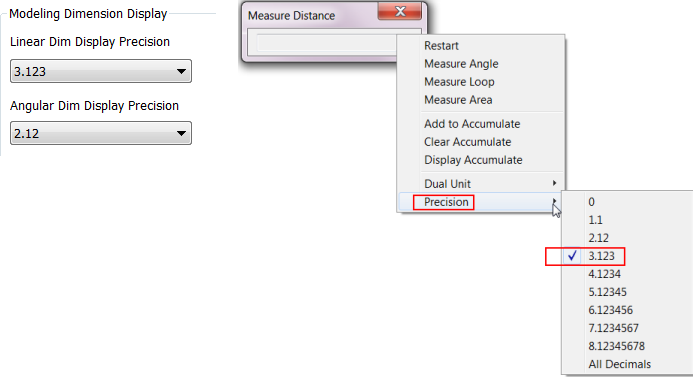
Important: When you create a new template file in any new version of Inventor (for example Inventor 2017 R2, R3, 2018, and onward) the default measure precision value must be set in
both
Document Settings  Units tab Modeling Dimension Display fields and in the Measure Precision value dialog box.
Units tab Modeling Dimension Display fields and in the Measure Precision value dialog box.
Measure Linear Distance or Length
Measurements display in the Measure dialog box. The dialog box title changes to reflect the measurement type.
- On the ribbon, click
Tools tab
Measure panel
Distance. Or, click Measure on the marking menu.
- In Inventor assemblies only, click the arrow on the left to choose selection priority: Component, Part, or Edges and Faces.
- In the graphics window, click to select geometry to measure:
Note: You can restart Measure by clicking in the graphics window.
- Length of an edge, Click to select the edge.
- Diameter of a cylindrical face or circle Pause the cursor over the cylindrical face or circle until a diameter line appears, and then click to select it.
- Radius of a cylindrical face or arc Pause the cursor over the cylindrical face or circle until a radius line appears, and then click to select it.
- Position of a point from the origin Click to select the point. The position of the point relative to each axis of the active coordinate system displays.
- Distance between points Click to select the first point, and then click to select the second point. When you select the second point, the position of the point from the origin and delta position relative to the first point displays.
-
Distance between two components in an assembly (not available in Inventor LT) Select the first component, and then select the second component. A minimum distance value displays. The minimum distance between two components can be an edge, face, or vertex.
Note: Changing the priority also changes the type of minimum distance measurement you can perform, such as minimum distance between components or parts. The command defaults to Select Faces and Edges priority. When you use Component Priority in an assembly, you can select only components as valid selections, not faces. Changing the selection priority after the first selection resets the command.
- Arc length Select an arc.
Note: You can also right-click in the graphics window, select Measure, and then click an option.
Tip: Use Select Other to choose the appropriate measurement. For example, if you click an arc, use Select Other to choose between the arc radius and arc length measurements.
Measure Angle, Loop, or Area
- On the ribbon, click Tools tab. In the Measure panel, click Angle, Loop, or Area.
- In the graphics window, click to select the geometry to measure.
- To measure the angle between two lines or edges, click to select one, and then click to select the other.
- To measure the angle between points A and C, relative to the origin B, click points A, B, then C. The returned value is the angle between vectors BA and BC.
- To measure an area, click the contiguous, enclosed region to measure.
Use Measure to Enter Values in Dialogs
In most dialog boxes, you can use the Measure command to enter values .
- In a dialog box, on the drop-down list for a box that requires a value (for example, Taper or Distance in the Extrude dialog box), click Measure.
- In the graphics window, click to select the geometry to measure.
The measurement displays.
Accumulate Values of Several Measurements
Add the values of several linear measurements to calculate a total measurement.
- On the ribbon
Tools tab
Measure panel
, click
Distance
or
Angle.
- In the graphics window, click to select the geometry or distance to measure. The measurement displays in the Measure Distance dialog box.
- In the dialog box, in the drop-down list, click Add to Accumulate.
- Continue adding measurements to accumulate.
- When finished adding measurements, on the drop-down list click Display Accumulate. The sum of the measurements displays.