Sets preferences for sketching.
Access
File  Options
 Sketch tab
2D Sketch preferences
Constraint Settings
Settings
Control settings for display, creation, inference, relax dragging and over-constraint for sketch constraints and dimensions. You can select the constraints to remove during relax dragging in the Relax Mode settings; you can choose not to create constraints automatically by turning off the Constraint Inference option.
Spline fit method
Sets the transition of the spline curve between points. Determines the initial type of solve for a spline.
- Standard
-
Sets the fit method to create a spline with smooth continuity (G3 minimum) between points. Suitable for Class A surfaces.
- AutoCAD
-
Sets the fit method to create a spline using the AutoCAD fit method (G2 minimum). Not suitable for Class A surfaces.
- Minimum Energy
-
Sets the fit method to create a spline with smooth continuity (G3 minimum) and good curvature distribution. Suitable for Class A surfaces. Takes the longest to calculate and creates the largest files.
Note: If you adjust the spline tension of an existing spline, it is converted to a Minimum Energy fit method regardless of the fit method used to create it. - Minimum Energy - Default Tension
-
Sets the slider bar to a pre-determined tightness or looseness for a 2D spline. If a 2D spline created using a Standard or AutoCAD fit method is converted to a Minimum Energy spline, the slider setting is used.
Note: In a 2D or 3D sketch, the context menu option Spline Tension presents a dialog box with a slider bar. Use it to adjust the spline tension independent of the Application Option setting. For a 2D spline, in the Spline Tension dialog box, click Default to write the current tension setting to the Application Options.
Display
Sets the elements of the coordinate system and grid to display when sketching. Select the check box to display the element. Clear the check box to hide the element.
 Options panel
 Document Settings
  Sketch tab.
- Grid lines
-
Sets the display of grid lines in sketches
- Minor grid lines
-
Sets the display of secondary or minor grid lines in sketches.
- Axes
-
Sets the display of sketch plane axes.
- Coordinate system indicator
-
Sets the display of the coordinate system for the sketch plane.
Heads-Up Display
Enable Heads-Up Display (HUD)
The Heads-Up Display activates Dynamic Input so that numeric and angular values may be entered directly into the value input boxes when creating sketch geometry. Click the Settings button to open the Heads-Up Display Settings dialog box and change settings.
Heads-Up Display Settings dialog
- Enable Pointer Input
-
When active, the starting point for a sketch element is displayed as Cartesian coordinates (X and Y values) in the value input boxes near the cursor. Disabling Pointer Input turns off the coordinate display of the starting point of a sketch element.
- Pointer Input options
-
Use to switch the starting point for a sketch element between Cartesian and Polar coordinates.
- Cartesian Coordinates
-
When selected, the starting point of a sketch element is displayed with X and Y values relative to the sketch origin of X = 0, Y = 0. This is the default setting.
- Polar Coordinates
-
When selected, the starting point of a sketch element is displayed with length (L) and angle (A) values relative to the sketch origin of X = 0, Y = 0.
- Enable Dimension Input where possible
-
When active, values are entered using a combination of both regular Cartesian and Polar coordinates depending on the type of sketch element being drawn. Dimensions are automatically placed on sketch geometry when the TAB key is used to toggle between value input fields.
When this setting is disabled, values are entered using Delta X and Delta Y Cartesian coordinates only. Polar coordinates cannot be used. Dimensions are not placed on sketch geometry even when using the TAB key to toggle between value input fields.
Dimension Input options
- Cartesian Coordinates
-
When selected, both positive and negative Cartesian X and Y coordinates are entered. The values are calculated based on the last pick point.
- Polar Coordinates
-
When selected, values are entered using a combination of regular Cartesian and Polar coordinates depending on the type of sketch element being drawn. The values are calculated based on the last pick point. This is the default setting.
Snap to grid
Sets the snap behavior for sketching tasks. Select the check box to turn on snap. Clear the check box to turn off snap.
Autoproject edges during curve creation
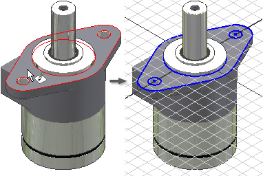
Enables the capability to select and project existing geometry to the current sketch by "rubbing" the existing lines. The lines are projected as reference geometry. Select the check box to use Autoproject. Clear the check box suppress Autoproject.
Autoproject edges for sketch creation and edit
When you create or edit a sketch, automatically projects the edges of the selected face onto the sketch plane as reference geometry. Select the check box to create reference geometry automatically for new and edited sketches. Clear the check box to suppress creation of reference geometry.

Look at sketch plane on sketch creation and edit
When selected, specifies that the graphics window reorients so that the sketch plane is parallel to the view for new sketches. Clear the check box to create a sketch on the selected sketch plane regardless of orientation to the view.
- When creating or editing a part sketch.
- When creating or editing a component in part.
- During in-place edit of a part within an assembly.
In Assembly Environment controls Look at behavior when creating or editing an assembly sketch.
Autoproject part origin on sketch create
Specifies preference for projected part origin on new sketches. The check box is selected by default. Clear the check box to project the origin manually. Not available in Inventor assembly sketches.
Point alignment
When selected, infers alignment between endpoints of newly created geometry and points of existing geometry. Temporary dotted lines are shown to indicate the inferred alignment.
If not selected, inferred alignment relative to specific points can be temporarily invoked by passing the cursor over the points while in the sketch command.
Enable Link option by default during image insertion
Sets a default to enable or disable the Link check box in the Insert Image dialog box. The Link option allows changes that are made to an image to update in Inventor.
3D Sketch
Auto-bend with 3D line creation
Automatically places tangent corner bends on 3D lines as you sketch them. Default setting is off. Select the check box to place corner bends automatically. Clear the check box to suppress automatic creation of corner bends.
Sketch Display
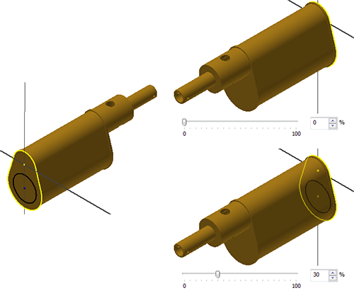
The Opacity of sketch displayed through shaded model setting controls the degree to which sketch geometry is visible through shaded model geometry. Default setting is 0%, which sets the sketch geometry to be completely obscured by shaded model geometry. Change the value to enable the sketch geometry to bleed through the shaded geometry.

Import
- Import
- Imports Application Options settings from an .xml file. Click Import to display the Open dialog box. Navigate to the desired file, and then click Open.
- Use AutoCAD Related Settings
- Provides a feel similar to AutoCAD settings.
- Use Inventor Settings
- The default Application Options settings are installed.
Export
- Export
- Saves the current Application Options settings in an .xml file. Click Export to display the Save Copy As dialog box. Select a file location, enter a file name, and then click Save.
Note on default install locations for both Import and Export operations:
Inventor. Microsoft Windows 7 and Windows 8: Users\[login]\AppData\Local\Autodesk\Inventor [version]\Preferences.
Inventor LT. Microsoft Windows 7 and Windows 8: Users\[login]\AppData\Local\Autodesk\Inventor LT [version]\Preferences