When creating and editing a sketched route, a series of commands are used to define route points based on the 3D Orthogonal Route tool. For instance, these commands include Custom Bend, General Dimension, Constraints, Parallel With Edge, and Perpendicular To Face.
Different commands are dependent on your route edit environment and design purpose. Similarly, when geometry is available to snap, you can apply Point Snap and Rotation Snap to rigid piping and bent tubing routes.
- Use Point Snap to assist in creating route points by snapping to faces, edges, work points, or vertices.
- Use Rotation Snap to assist in controlling the route direction by snapping the direction axis of the 3D Orthogonal Route tool to available edges and faces.
Use Point Snap
- Set your active project to the AirSystemAssy.ipj under the installation location of Autodesk Inventor. The default location for XP is: C:\Program Files\Autodesk\Inventor<version>\Tutorial Files\Tube & Pipe.
- Open AirSystemAssy.iam and create a master runs assembly along with the first active run. For detailed instructions, see Create tube and pipe runs.
- Use the ASTM A53/A53M-ASME B16.11 - Welded Steel Pipe style to create two routes using the auto route solution as shown in the following image.
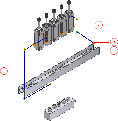
1: Route1 2: Route2 3: Route Point 4 in Route2 4: Route Point 5 in Route2
-
 Optionally, if the 3D Orthogonal Route tool is not active, right-click Route Point 5 in the Graphics window and select Edit Position.
 - With Route2 active, right-click in the graphics window, and select Point Snap.
- In this exercise, do not add dimensions to the next route segment. Right-click again and clear the Auto-Dimension check box.
- Pause your cursor over the route point in Route1 as shown in the following image. When the dashed line shows the snap point, click to create the route point at the intersection with the command.
- Right-click the point you just created, and click the Route command to continue the route.
- Click the snap point, and click the Route command to continue the route.
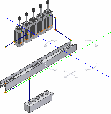
- Do the following to add two subsequent route segments using 45-degree Angle Control.
- Pause the cursor over the direction axis, and enter a distance of 2.25 inches for the next point.
- Click the 45-degree Angle Control to change the angular position to the left, and then add a route segment distance of 3.5 inches on the line extender.
- Click the 45-degree Angle Control so that the direction axis is parallel to the valve.
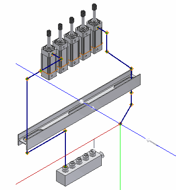
You should have the result as shown in the following image:
- Ensure that the Point Snap check mark is selected on the context menu.
- Right-click the circular edge on the valve as shown in the following image, and click Select Other Snap.
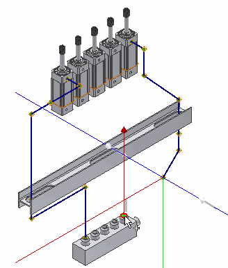
- When the preview point is displayed at the intersection of the line and the axis, press Enter to set the snap point.
- For the last point, click the circular geometry as in Step 12.
- Right-click and select Done.
- Right-click and select Finish Edit.
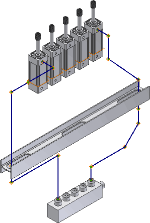
Use Rotation Snap
During forward creation, use the Rotation Snap command to change to the orientation of a specified direction axis that is snapped to available planar edges and face geometry. It is available when the 3D Orthogonal Route tool is displayed for forward route creation and works with the rotation handles on the 3D Orthogonal Route tool.
|
3D Orthogonal Route tool for rigid piping routes, excluding tools displayed for defining a custom bend: 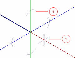 |
3D Orthogonal Route tool for bent tubing routes, including tools displayed for defining a custom bend in rigid piping routes: 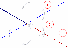 |
1: Rotation handles 2: 45-degree angle controller 3: Radius handles (for bent tubing routes only)
-
 In forward route creation environment, ensure you are working on a free terminal route point, and then click Route tab
  Create panel
  Route so the 3D Orthogonal Route tool is displayed. You can use any of the following approaches to display the 3D Orthogonal Route tool if it is not already displayed:
 - On the ribbon, click Route tab
 Create panel
  Route , and then click the route point in the Model browser or graphics window.
 - Click the route point, and click Route tab
 Create panel
  Route .
 - Right-click the route point, and select Route.
- On the ribbon, click Route tab
- Right-click in the graphics window and select Rotation Snap.
- On the 3D Orthogonal Route tool, click a rotation handle and drag the cursor on to a planar edge or face geometry you want to snap.
The geometry is highlighted and a dashed line intersects with the direction axis at the new orientation.
- Release the cursor to set the direction axis to the new orientation.
- If the Point Snap command is already selected, continue to create additional snap points based on appropriate geometry.
- Continue with forward route creation.
 Show Me how to use Rotation Snap and Point Snap