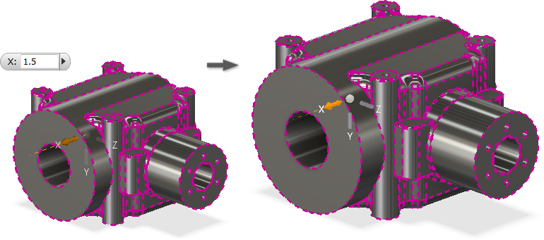
Use Direct Edit to make changes to solids created in Inventor and to imported solid models that have no history.
Parameter values are created when you add a direct edit, and you can edit the values in the Parameter dialog box. You can also continue to make changes using the Direct Edit operation and the parameter values update correspondingly.
Direct Edit provides a mini-toolbar with four edit operations (Move, Size, Rotate, and Delete) and a direct-manipulator triad that you use to modify the model.
After applying a direct edit, the browser shows the direct item entry. A corresponding glyph displays in canvas. The operation creates parameter that can be controlled in the Parameters dialog box.
Move or Rotate Faces or Solids Using Direct Edit
- Click 3D Model tab
 Modify panel
  Direct Edit
  .
. - In the Direct Edit mini-toolbar, specify the operation you want to perform and the geometry you want to affect:
- Move. Activates the triad manipulator for Move operations. Relocates the selection and extends adjacent geometry.
- Rotate. Activates the triad manipulator for Rotate operations.
- Faces. Enables faces for selection.
- Solids. Enables solids for selection.
- In the graphics window, select the items to move or rotate.
- Drag one or more triad handles, enter a parameter name, or enter a precise value for the move distance or rotation angle.
Move manipulators:

Rotate manipulators:

- Use the following as needed:
- To relocate the triad, select Locate
 . The triad appears on your cursor. Place the triad on the new desired location.
 - Control the triad orientation with the World and Local options:
- To align the triad to the geometry, first select Local, and then select
 on the mini-toolbar. Local places the triad relative to the face or body selected.
 - To orient the triad with the part origin, select World. With World, the alignment selection is not available.
- To align the triad to the geometry, first select Local, and then select
- To relocate the triad, select Locate
- If desired, select any of the following:
Move
- Measure From. Controls the start location for the distance by selecting existing geometry as a reference. You can measure from most geometry types including sketch and work geometry.
- Snap To. Creates and maintains alignment with other geometry.
Rotate
- Snap Parallel. Creates and maintains parallel alignment with another face. This is a planar face selection only. Note: With Snap To and Snap Parallel, associativity across parts in an assembly is not maintained.
- Click Apply in the mini-toolbar.
Resize Faces Using Direct Edit
- Click 3D Model tab
 Modify panel
  Direct Edit
  .
.
Delete Faces Using Direct Edit
- Click 3D Model tab
 Modify panel
  Direct Edit
  .
. - In the Direct Edit mini-toolbar, select Size. Note: The Solids selector is not available for Delete operations.
- In the graphics window, select the faces to size. Note: The parametric hole feature cannot be resized to avoid inaccuracy in drawing files.
- In the mini-toolbar, select a modifier:
- Offset. Offsets selected faces at a given distance from the selection.
- Diameter. Changes the size of cylindrical faces. Differently-sized cylindrical features are changed to the same diameter.
- Radius. Changes the size of radial faces. Differently-sized radial features are changed to the same radius.
Note: The active modifier controls the faces filtered from the selection set. - In the graphics window, drag the manipulator handle. For example, to change the radius of an object, select the Radius modifier, and drag the manipulator handle or enter a value in the input box.

- Click Apply in the mini-toolbar.
Scale Solids Using Direct Edit
- Click 3D Model tab
 Modify panel
  Direct Edit
  .
. - In the Direct Edit mini-toolbar, select Scale. Note: The Faces selector is not available for Scale operations.
- In the graphics window, select the solid to scale.
- In the Mini-toolbar, select a modifier:
- Uniform. Scales the solid using a single factor.
- Non Uniform. Scales the solid using separate X, Y, Z scale factors.
- In the graphics window, drag the manipulator handle or enter a value in the input box.

- Click Apply in the mini-toolbar.
Modify a Direct Edit
- Do one of the following:
- Double-click a direct-edit glyph in the graphics window.
- Right-click a direct-edit glyph in the graphics window and choose Edit.
- Double-click or right-click a direct-edit browser entry.