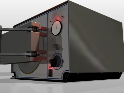
Inventor and Inventor Professional: You can use the various Studio commands to give your components a more realistic appearance, add props, lighting, and camera positions that highlight the beneficial aspects of your product.
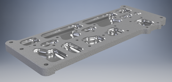
Inventor LT: You can use the various Studio commands to give your model a realistic appearance, lighting, and camera positions that highlight the beneficial aspects of your product.
Props in Inventor and Inventor Professional
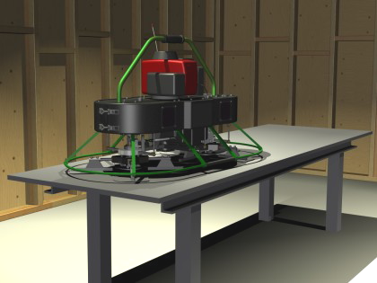
Props can add visual stimulus, denote scale, or tell a brief story about your product. For example, if your products are hand tools. Use a tool box as a prop, placing your tools in one or more drawers of that tool box. If you plan to use props in your scene, consider the use of a scene or wrapper assembly.
Common Styles Workflow
Regardless of the style type (lighting or scene) there are common aspects to the workflow for creating new styles and editing existing ones.
These commands are typical and accessed from a style context menu.
- New Lighting Style Creates a new style using predetermined application defaults.
- Copy Lighting Style Duplicates the style and all of its settings.
- Rename Lighting Style Edits and highlights the style name so all you need do is enter a new name.
- Export Style Saves the selected style in a formatted XML file so that it can be shared between users.
Measure Command and Frequently Used Values
To use the Measure command or choose from most recently used values, click the arrow associated with the input box and select from the list.
Lights and Cameras
Cameras and Lights have geometric representations that can be used to modify position and location of both the target and source. Their edit behaviors are similar. Light and Camera targets and positions, when selected, can be moved using the triad associated to the selection. Use the ViewCube to adjust the view during the process. The direction line between the source and target is also selectable during edit and enables moving of the light or camera.
The graphical representations of cameras and lights can be turned off to reduce visual clutter in the scene. Changing the visibility does not affect the scene output, however, changing the Enable setting will include or exclude light contribution.
Copy and Paste commands
You can copy and paste cameras and lights using the context menu commands or the standard Copy/Paste commands. The copy is placed next to the original in a selected state ready to move and edit.
You can also edit the target and position elements in the graphics region. Click the target or position glyph, the move triad appears as well as the 3D Move/Rotate dialog box for explicit values.
Lighting Styles
Use Lighting Styles to illuminate scenes. A Studio lighting style is based on one Environment lighting source and, optionally, one or more studio lights. Studio lights can be directional, point, or spot type. Set environment light parameters Source, Exposure, Rotation, and Scale. If you add Studio lights, adjust light parameters to meet your needs. Inventor Studio provides several lighting styles for your use or you can create new ones.
Cameras
Cameras are used to establish the viewing angle for the scene. Careful consideration with respect to the viewing angle and camera type improves the rendered image. Cameras can be animated in a variety of ways, such as a camera turntable, animated along a path, and freeform (non-path).
You can create and maintain as many cameras as you want in the scene. Cameras are saved with the model and can be recalled during any Inventor Studio session. Cameras may also be deleted from the scene.
There are two types of cameras, orthographic and perspective. Orthographic cameras are typically used to produce standard and isometric style images. Perspective cameras are used when you want the impression of depth in your image or when the rendered output is combined with a photograph. Use various camera parameters, such as orthographic and perspective, camera roll, zoom, and depth of field to achieve the results you need for your images and animation.
Camera Settings
The zoom angle of the camera, and distance from the target to the position determine the width of the square. The height of the square respects the aspect ratio defined by the stored rendering settings. For example, if the rendered image size is 640 x 480, the height of the square is 3/4 the width. A shape that is a combination of a truncated pyramid and a box is displayed at the position point. The roll marker, a small black vertical line at the middle of the top edge of the view volume square, indicates the up direction of the camera and is also a handle used to adjust the roll angle.
Depth of Field
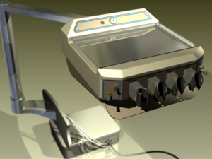
Depth of field has two parameters, Near and Far, represented as planes. Objects situated between those values are in focus. Objects outside the values become increasingly out of focus the farther they are from the Near/Far values.
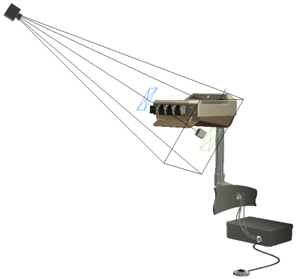
You can use the output from one or more cameras, either still or running shots, to compose a video animation. See Video Producer reference.
Local Lights
Local lights provide the means to create lighted objects, such as lighted switches, panel lights, and so on. Some limitations apply.
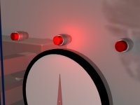
Inventor Studio provides local light objects, point and spot lights, for use with self-illuminated components in part and assembly models. Local lights exist as a child of the component in which they are placed. If the component is animated, the local light moves with its parent component. Examples of self-illuminated components are panel lighting, device lights, lighted buttons, headlights, flashlight bulb, dashboard light, and so on.
Local lights can also be used at the component level and also at the assembly level.
Component level
Add a local light to a component to have a light that travels with the component when it is animated. The light parameters are static in this case, that is, whatever the parameters are set to remains the condition throughout the animation. Local light parameters cannot be animated when the light is lower than the top level of the model hierarchy.
Local lights can be the only object in a component model. You can create a model, exit the sketch, add a local light and position the light relative to the model origin work features. You can position a light within the assembly relative to other components or work features. The component position can then be animated using either Animate Component or Animate Constraints.
For BOM purposes, this component should be set as a Reference component.
Assembly top level
Adding a local light to the top level of the assembly allows certain light parameters to be animated. The light is not associated with a part in this case.
Rendered Image
If the rendered scene is to be combined with a photograph in post edit, then render it using a perspective camera and camera angle similar to that in the photograph. Attempt to simulate the lighting conditions and shadow direction as best you can.
To output an image with a transparent background, for compositing with another image, the PNG with alpha channel must be selected in the Save Options dialog box before rendering.