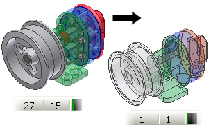
The Shrinkwrap command creates a part from an existing assembly. The shrinkwrap part is a simplified version of the source assembly that can provide a significant reduction in file size in consuming assemblies or applications. Use the hole and geometry removal tools to help protect intellectual property. The default method creates a single surface composite. A surface composite is the fastest method and creates the smallest file of the three options.
- Access
-
-
Ribbon:
Assemble tab
 Component panel
  Shrinkwrap

-
Ribbon:
Assemble tab
 Component panel
  Shrinkwrap Substitute

-
Ribbon:
BIM Exchange tab
 Manage panel
  Substitute Shrinkwrap Substitute
-
Ribbon:
Assemble tab
Assembly Shrinkwrap Options
- Style
-
 Single solid body merging out seams between planar faces
- Select to produce a single solid body without seams between planar faces. When you merge seams between faces, the face assumes a single appearance.
 Solid body keep seams between planar faces
- Select to produce a single solid body with seams between planar faces retained.
 Maintain each solid as a solid body
- Select to produce a multi-body part that contains a unique body for each part in the assembly.
 Single composite feature
- This is the default selection. Select to produce a single surface composite feature. This selection produces the smallest file. Appearances and seams of the original components are retained. The mass properties of the original assembly are cached. and retained.
- Preview
- Select to visualize the results of the current selection settings in the dialog box. If options are changed, reselect Preview to see the effects of the change.
- Simplification
- Remove geometry by visibility Select the check box to enable the options to remove geometry based on visibility. The check box is selected by default.
Whole parts only Parts which meet the visibility criteria are removed. Individual faces which meet the visibility criteria are not removed.
Parts and faces Removes any face including entire parts which meet the visibility criteria. The default setting is on.
Visibility percentage A value of zero removes all parts or faces that are not visible in any view. Increasing the slider value removes more parts and faces.
Ignore surface features for visibility detection Available if Remove geometry by visibility is enabled. If enabled, surface features do not affect visibility detection. If not enabled, surface features participate in visibility detection and can hide geometry.
Remove parts by size Select to enable the option to remove parts based on the size ratio. The ratio indicates the difference between the part bounding box and the assembly bounding box.
- Hole Patching
- Does not remove any holes.
All Removes all holes that do not cross surface boundaries. Holes do not need to be round to be included. It is the default setting.
Range Specifies the circumference or perimeter of the holes to include or exclude. Holes do not need to be round to be included.
- Include other objects
- Work Geometry
When selected, any visible work features in the component are exported and can be derived.
Sketches When selected, any visible and unconsumed 2D or 3D sketch in the component are exported and can be derived.
iMates When selected, any iMates defined in the source assembly are exported and can be derived.
Parameters When selected, any parameters in the source assembly are exported and can be derived. The Parameters folder includes a subfolder that contains folders from the Parameters dialog box. The Parameters and Export Objects dialog boxes share the same parameter statuses.
- Use color override from source component
- Select to link color from the base component into the target part. If unchecked, the appearance is set to default appearance of the target part.
- Break link
- Permanently disables any updates from the source component.
- Remove all internal voids
- Select to fill all internal void shells in the shrinkwrap solid body part.
- Reduced Memory Mode
- When the check box is selected, a part is created using less memory by excluding source bodies from the cache. No source bodies appear in the browser. Breaking or suppressing the link removes the memory savings. Turned on by default.
- Create independent bodies on failed Boolean
- When the check box is selected, a multi-body part is created when a Boolean operation fails on a single solid body style option.