Joint

The Joint command is a simple way to position components and describe motion. Creating a joint fully defines the component location and motion in one step. End, mid, and center points are used to associatively position components. The geometry you select determines the default joint type, or you can specify a joint type.
The following describes the joint types and how they operate while positioning a component:
-
 Rigid
Rigid
- Removes
all degrees of freedom (DOF). Welded and bolted connections are examples of a rigid joint.

-
 Rotational
- Specify
one rotational DOF. Hinges and rotating levers are examples of a rotational joint.

 Slider
- Specify
one translational DOF. A slide block moving along a track is an example of a slider joint.

-
 Cylindrical
- Specify
one translational and
one rotational DOF. A shaft in a tube is an example of a cylindrical joint.

-
 Planar
- Specify
two translational and
one rotational DOF perpendicular to the linear. To place a component on a planar face, use this joint type. The component can slide or rotate on the plane.

-
 Ball
Ball
- Specify
three rotational DOF. A ball and socket are an example of a ball joint.

- With the addition of the joint command, both constraints and joints are now described as relationships.
- In the browser, the Constraints folder is renamed to Relationships, and displays in both the Assembly View and the Modeling View.
- You can use joints with constraints to position components and describe motion.
For more information, check out the new Place and connect parts interactive tutorial or click here.
Inventor joints are automatically converted to simulation joints when you enter the Dynamic Simulation environment. The converted connections are listed as standard joints in the simulation environment browser. The following are the automatic conversions:
| Inventor joint | Joint in Dynamic Simulation |
| Rigid | Welding |
| Rotational | Revolution |
| Slider | Prismatic |
| Cylindrical | Cylindrical |
| Planar | Planar |
| Ball | Spherical |
You can edit the joints that are created automatically in Dynamic Simulation using the context menu in the browser.
Joints locked in the Assembly environment are also locked in Dynamic Simulation. To unlock a joint, right-click and clear the selection for Lock dof.
Lock and Protect
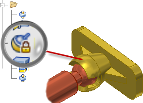
- Lock maintains the current position, but is different from grounding a component. Lock eliminates all motion, but allows the component to change position when related components move. Grounding eliminates all degrees of freedom, and fixes the component position in space.
- Protect alerts you if an added relationship violates the required degrees of freedom.
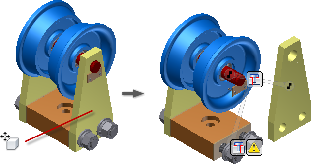
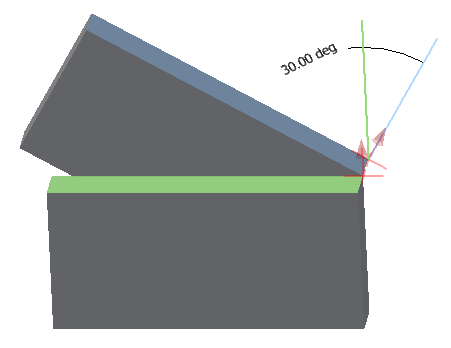
In the following image, the Ball joint connection is locked.
Relationship display commands
-
 Show
Show
-
 Hide All
-
 Show Sick
To display a glyph that shows the relationship type, select a component. To suppress, unsuppress, or delete a relationship, use the glyph context menu.
Remove all relationship glyphs from the display. Hide All does not modify relationships.
Display all relationships that are marked sick. To suppress or delete a relationship, use the glyph context menu.
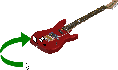
Grounded component display
You can easily identify grounded components in the display. The grounded icon appears when you move your mouse over a grounded component.
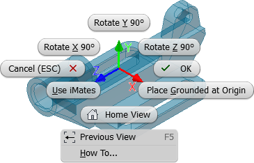
Place Component
A new assembly application option specifies whether to ground the first placed component at the origin. This new option is turned off by default. To ground any component at the origin, use the context menu. The menu contains new options to rotate components in 90-degree increments about the X, Y, or Z axis, before you place them in the assembly.
Free Move
With the Free Move command, display relationships as an elastic band, and visualize and manage relationships in a new way. Click a relationship icon, and then, to suppress, unsuppress, or delete relationships, use the context menu.
Assembly copy paste
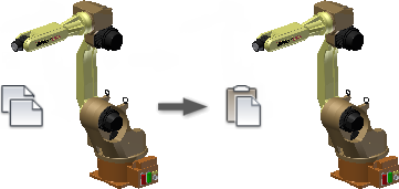
In previous releases of Inventor, a copy and paste operation did not retain component connections or current orientation.
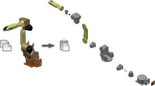
The enhanced copy and paste operation produces a duplicate of the copied components with connections and orientation intact.
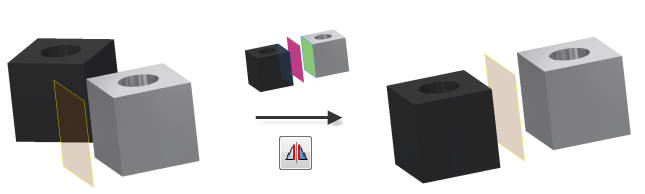
Symmetry constraints
The Symmetry constraint positions two objects symmetrically according to a plane or planar face. The Symmetry constraint is available in the Place Constraint dialog box.
Improvements in Angular constraints
When you create an angular constraint, the status bar displays clear instructions to finish the Constrain command.
Angular constraints display direction vectors and the angle in the graphics window.
The model preview updates when the Angle value changes.
Express mode for large assemblies
Express mode introduces a new way of working with large assemblies. Large assemblies typically open 4-6x faster, dramatically improving your time to work.
Enable the Express option and set the unique files threshold in the Application Options, Assembly tab. Large assemblies that exceed the threshold open automatically in Express mode.
 Load Full
to exit Express mode and enable all commands.
Load Full
to exit Express mode and enable all commands.
Improved graphics performance
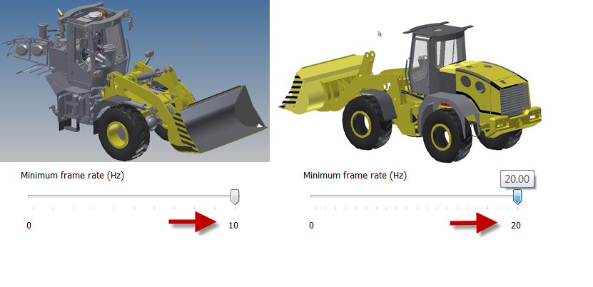
- The maximum frame rate is increased from 10 Hz to 20 Hz.
- The largest objects are drawn first.
- The graphics system now uses multiple cores to provide the best possible performance.
- A new background operation called consolidation is added. Consolidation draws objects that have the same appearance as a single group, improving the GPU usage.
In the following images, the 2013 model on the left displays the results of rotating the model using the maximum of ten frames per second. Increasing the frame rate increases the speed, but the choice of components to draw is not intelligent. The 2014 model on the right shows the results of rotating at the faster maximum frame rate of 20 Hz. The model remains recognizable, and all view operations are faster.
Enhancements in Insert Frame command
In previous versions of Inventor, construction lines and center lines are automatically included, and frame components are created from them.
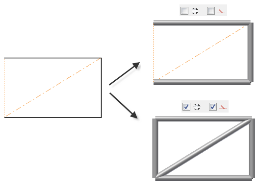
In the current version, you can exclude construction lines or center lines from the geometry selection used to create frame components.
On the ribbon, click
Design tab  Frame panel
Insert Frame
Frame panel
Insert Frame
![]() . Then, in the Insert dialog box, select or clear the Select Centerline, or Select Construction options to specify your settings.
. Then, in the Insert dialog box, select or clear the Select Centerline, or Select Construction options to specify your settings.
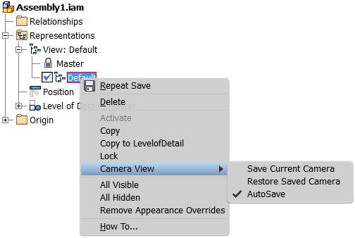
Camera setting in view representations
In previous versions of Inventor, the camera position is always automatically saved on closing the design view representation. When you rotate or zoom the model in a design view, tools to restore the previous camera settings are limited.
With new commands in the view representation context menu, you can easily save and restore the camera settings.
- Save Current Camera command saves the current position of the camera, and switches off the AutoSave command.
- Restore Saved Camera command restores the last saved position of the camera.
- AutoSave command saves the last camera position automatically on closing the view representation. This option corresponds to the legacy behavior.
Improved export of recorded driven constraint sequences
The default settings used to export recorded driven constraint sequences are optimized. As a result, the WMV or AVI export provides optimal output quality by default.
When you customize settings in the WMV or AVI export dialog boxes, your customization is persistent for the entire session.
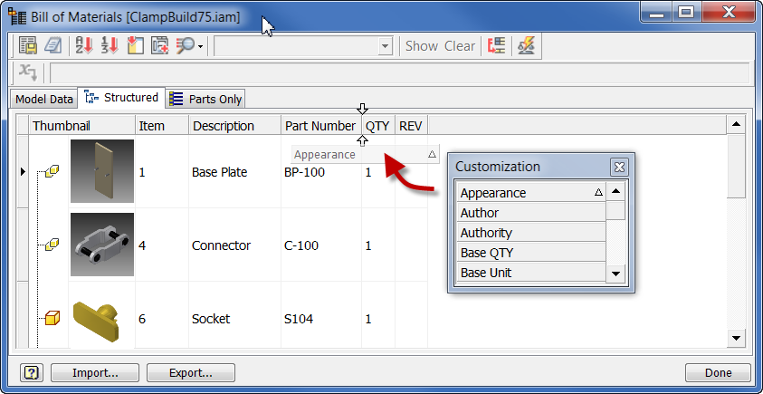
Appearance property
The model Appearance value is added as a selectable property. You can add the Appearance property to a bill of materials or a parts list.
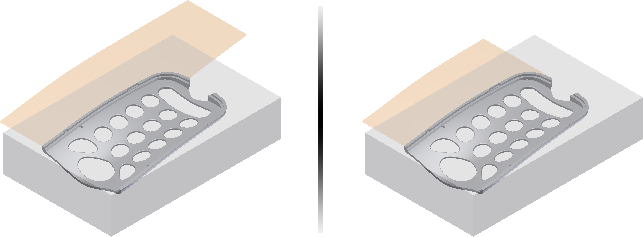
Mold design, Extend Runoff Surface
The Core/Cavity environment contains a new command for creating runoff surfaces. Previously, all tooling runoff surfaces were created along the XY plane or a user specified direction.
Use Extend Runoff Surface to create runoff surfaces that extend along the component tangent or rule. For example, the following image displays a tangent runoff surface on the left, and a rule runoff surface on the right.