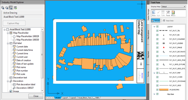
In this tutorial, you will create a plot that uses an AutoCAD block as a frame, instead of using the normal plot decoration features.
Prerequisites
To perform this tutorial successfully, you should be familiar with the following aspects of AutoCAD and AutoCAD Map 3D, and enterprise industry models :
- What AutoCAD blocks and AutoCAD block references are, and how to use AutoCAD's block editor
- How to use the Display Manager
- How to use projects , industry models , feature classes, features, and generic forms
- How to create a display model and set up a repository path
- How to create and edit an enterprise industry model plot, and use the Plot Library
Assumptions
Before performing this tutorial, the following should be true:
- You have created a project
- You have imported the Land Management demo dump and named the industry model PLOT_ACADBLOCKS.You have enabled the Plot Extension for that industry model.
- You have set up the repository path for your display models correctly.
- You have copied the default display model for plots to a sub-directory of your display model repository path, and adjusted all settings.
To create a plot using AutoCAD blocks
- In the Maintenance workspace, open an enterprise industry model project.
- Generate graphics and zoom to the area of interest.
- Display the Plot Explorer in the Industry Model explorer using either of the following methods:
- Click .
- Click Plot Explorer in the Industry Model explorer.

The Plot Explorer pane opens to display your Plot Library. The Plot Library contains plot templates and any plots you have saved.
- Create a new plot.
- Use the settings shown below.
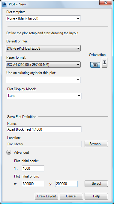
- Click Draw Layout to open the plot for editing.
- Close all open drawings except the one that contains the newly created plot.
- Use the settings shown below.
- In the newly created plot drawing, type BEDIT to open the AutoCAD Block Editor.
- Create a new AutoCAD block that is 297 units wide and 210 units tall (A4).
- Set the block’s base point to its center.
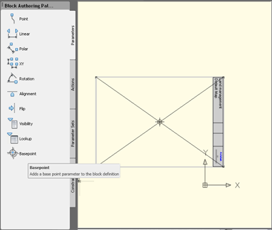
- Close the block editor.
- Style the layer PLT_PLOT_DECORATION.
- In the Display Manager, select the layer and click Style.
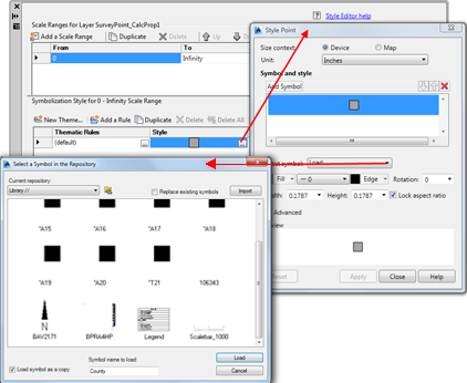
- In the Style Editor, under Point style 0 - Infinity Scale Range, click the browse button in the column labeled Style.Set the parameters as follows:
- Symbol: Select the block you just created from the current drawing.
- Size Context: Map space
- Units: Meters
- Width: 297 (A4, 1:1000)
- Height: 297 (this is set automatically when you set the width)
- Fill color: Keep the original color.
- Edge Color: Keep the original color.
- Rotation: Enter the expression ORIENTATION * 0.9 + 90
- Save the current display model, overwriting the existing plot display model.
This creates a new drawing named BlockDefinitions.dwg, which contains the block you just created.
- Digitize a new plot point decoration feature, as shown below.
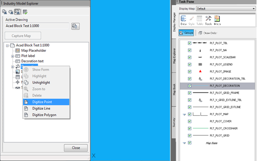
- Open the generic form for this point feature, and set its position to the center of the page, as shown below.
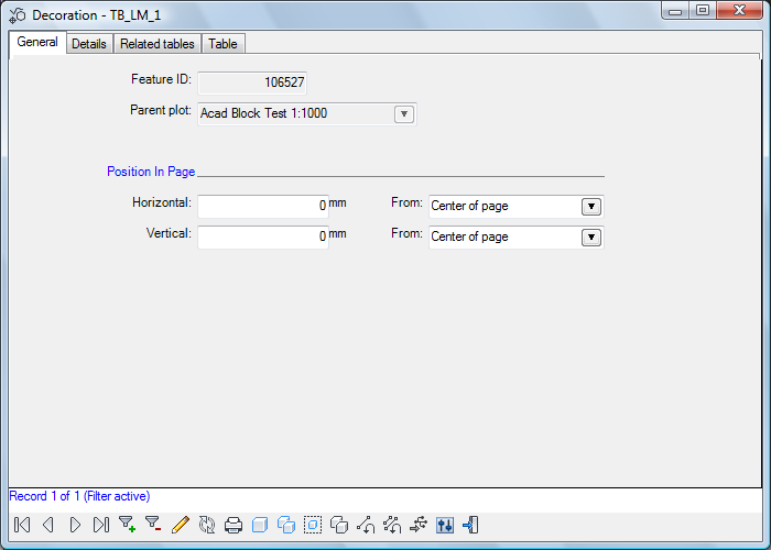
Once updated, the AutoCAD block will be centered on the paper.
The point decoration feature is styled using the AutoCAD block you created. This AutoCAD block has its base point set at its center. Because the point decoration feature is centered on the paper, the AutoCAD is correctly positioned.
- Optionally, create a (primary) map placeholder and set it to a pre-defined width and position.
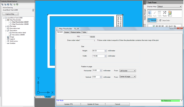
- Capture the map for this map placeholder.
- Specify an existing display model.
- Apply a rotation value, if necessary.
- Optionally, extend the plot by adding a label for the plot’s scale, an overview map, and any other desired elements.
The plot shown here is scaled at 1:1000.
