Shader Driven Update
The renderer is purely “shader based.” In other words, everything is rendered with a shader and shader requirements are the driving force to determine geometric data requirements. Changes in geometric parameters may require data updates, but they are with reference to the requirements of a shader.
When discussing “shaders,” these are not Maya shading networks but rather shaders that the renderer supports internally. All internal shaders are programmable hardware shaders and all recommended API interfaces also assume the usage of shaders. The concept of fixed-function rendering is no longer used nor exposed as a recommended method of drawing.
Each shader, whether used for drawing UI elements or for surface shading, specifies a set of data requirements. Requirements from all shaders affecting a renderable object are aggregated and used to inform the renderable object of the appropriate geometric data it needs to provide.
Both the shader specification and the geometric data may or may not be up-to-date. The change management mechanism propagates change requirements to both as required.
To illustrate this, a simplified scenario is shown:

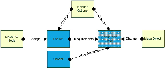
Figure 4: Shows two shaders and a renderable object and their change (dirtying) dependencies and data requirement dependencies.
The Maya constructs for the (top) shader and for the renderable object inform each, respectively, of any changes. The renderer itself (“Render Options”) may also propagate changes to both. A second (bottom) shader has no Maya object and could be used for UI drawing for instance. It also specifies requirements. When an update is required, all shaders provide requirements to the renderable object and the object fulfills those requirements by updating the appropriate geometric data.
The end result of the update phase is newly created or updated render items.
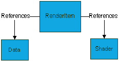
Each render item keeps track of both the shader as well as the data as a unit. Both shaders and data can be shared across different render items.

Figure 5: Data and shaders are independent of any individual render item and thus can be shared across multiple render items.
A concrete, though slightly contrived example of the above scenario would be as follows:
- A Maya object has been deformed.
- The Maya shader assigned to the object requires bump mapping.
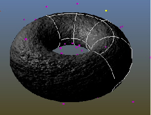
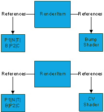
The Maya object informs the renderable object of a change in geometry (topological change). The Maya shading network informs its corresponding shader of a new shading algorithm requirement, namely tangents and bitangents. The renderer informs the renderable object of the requirement for a “UI” shader for drawing control points which requires a second set of positions and color. The aggregate requirement would then be two sets of positions and one set each of colors, normals, tangents and bitangents.


