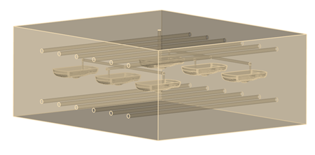
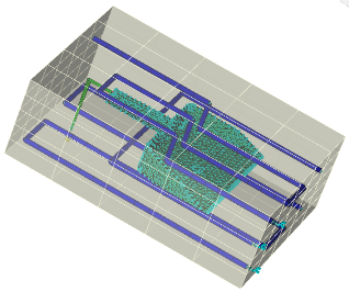
To run a Transient Cool analysis, in addition to the part model, you need the mold model with its associated cooling channels, hoses, baffles etc. and any additional components, such as mold inserts. If you don't have a mold model, you can use the Mold Block Wizard to create one.
The Mold Block Wizard enables you either to generate a mold block as a region, or to create a CAD mold. In either case, the cooling channels and feed system must be represented by underlying curves, and the parts and inserts must include their CAD representations, in order to be included in the mold mesh generation.
Mold block as a region
Mold block as a region is the default setting. When you click
 Mold Block Wizard, a message appears indicating that you are generating the mold block as a region. Inspect the dimensions, and adjust them if necessary, until you are satisfied. You can create a CAD mold block subsequently if you wish.
CAD mold block
You can create a CAD mold block in a single step, or you can create a mold block as a region, confirm that it is satisfactory, and then create a CAD mold from it. To generate a CAD mold in a single step, successfully, depends on the cleanliness of the part and insert. If the CAD part/insert has geometrical errors, it is likely that the CAD mold block generation will fail, or succeed with errors. Because it is important that your part/insert have no geometrical errors, CAD mold block generation is not set as the default option.