The accuracy of Autodesk Moldflow analyses highly depends on the correct sizing of meshing elements on all features of the model.
To meet Autodesk Moldflow solver requirements, it is important that your final surface mesh meet the following requirements:
- Provide an accurate representation of the model geometry: For example, curved features need to appear curved,
- Have an appropriate local mesh density: This means higher mesh density on small features, and lower mesh density on large features,
- Have a smooth gradation between mesh elements with different edge lengths,
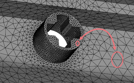
Example of an accurate mesh size setting
Once your model is meshed, check if any components or features of the model require a different mesh sizing. Pay particular attention to:
- Small features.
- Large, thin faces. You need enough mesh elements through the thickness of the part, to represent the part geometry accurately. Aim for an edge length that is less than 2.5 to 3 times the local thickness, especially if you plan to generate a 3D mesh eventually.
- Thin cylinders and thin holes. Make sure that at least 6 nodes make up their perimeters.
- The external boundary of mold blocks. Usually, the global edge length is defined for mold internal boundary that touches parts and other internal components. On another hand, the edge length on mold external faces should be larger, to save analysis time. We recommend setting a local edge length on external faces from 3 to 5 times the global edge length.
After identifying the areas that require local meshing settings, use local mesh density tool to adapt the local edge length and/or chord angle to the geometry of your feature.