This panel is used to define and create a finite-element mesh.
To access this panel, click
 ().
().
Dialog elements
| Widget | Explanation |
|---|---|
| Remesh already meshed parts of the model | If this option is selected and you click
Mesh Now, all visible sections of the model will be remeshed.
If this option is deselected and you click Mesh Now, only those sections of the model that are visible and have not been meshed already, will be meshed. Note: Remeshing a runner section or cooling channel at a different edge length is done via the
Curves tab.
|
| Place mesh in active layer | Places the mesh layer in an active Layer pane after creation. |
| Mesh Now | Initiates the mesh generation task immediately, either in the Cloud or on the local machine, depending upon your selection.
|
| Save Default Values | Saves all items marked with an asterisk as default, until you press this button again with other values. |
| Use Default Values | Restore the Default values. |
General tab
Determines what size elements will be created when the part is meshed, that is, the global mesh density.
| Widget | Explanation |
|---|---|
| Remesh boundary | Remeshes the part surface using the target edge length.
This option is available when you generate a Dual Domain mesh for a model which already has a 3D mesh. When this option is selected, existing nodes on the part surface are ignored and the part surface is remeshed using the target edge length. Otherwise, existing nodes used by the tetrahedral elements are reused for the Dual Domain mesh. |
| Preview | Shows the effects of your settings on the meshing process. Edge nodes that will be generated using the set values are shown. This allows the mesh density to be reviewed before you proceed with generating your mesh. |
| Global edge length on surface | Enter a value to set the target mesh element length that will be used when generating the mesh.
Note: Your edge length setting may be ignored in certain areas of your mesh if the setting is not appropriate. For example, if you specify a long edge length, your target edge length will be used in straight areas of the mesh, but a shorter edge length may be used in curved areas.
|
| Match mesh | Allows you to align the mesh elements on the two corresponding surfaces of a Dual Domain mesh. |
| Stop after surface mesh generation | When meshing a model in 3D, this option allows the surface mesh to be investigated before proceeding with the meshing of the volume of the part. Critical areas of the part can be reviewed to ensure an appropriate mesh density. |
| Calculate thickness for Dual Domain meshes (Dual Domain and 3D meshes only) | When meshing a model with the Dual Domain technology, this option allows for the thickness of the mesh to also be calculated. |
| Apply extra refinement near gates (Dual Domain and 3D meshes only) | A finer mesh surrounding the gate will better capture the heat transfer, higher shear rates and other critical properties that can rapidly change in this region. This option will refine the mesh around the gate and also any beam elements that are connected to the part. |
| Relative edge length (Dual Domain and 3D meshes only) | When the Apply extra refinement near gate option is selected, the Relative edge length determines the shorter edge length that is used to generate the finer mesh around a gate This is expressed as a percentage of the Global edge length used for the rest of the model. The default value is 20% of the Global edge length. |
| Source geometry type (Midplane mesh only) | Specifies the type of geometry that is to be meshed.
Note: This option is only available if your part contains NURBS surfaces.
In the Study Tasks pane, after specifying that you want to generate a Midplane mesh, in general, there are two possible tasks that the mesher can perform:
The following settings are available:
|
Curves tab
Curves are used to model the pathway of the feed system or cooling channels. Connected straight beam elements then follow this pathway. Factors such as the diameter, type of pathway (feed or channel) and bends within the path can affect the edge length prescribed to a beam element.
| Widget | Explanation |
|---|---|
| Use global edge length | Allows you to use the global edge length defined in the
General tab for the beams on your curves as well. Alternatively, define a length to diameter ratio.
The edge lengths are determined as follows: |
| Ratio of Edge length to diameter for Feed system | A default value of 0.75 for the ratio of edge length to feed system diameter is used for beams with the assigned property of Runner. The larger this ratio, the longer the feed system elements will be. To prevent unrealistic values being used, the ratio used must be between 0.1 and 4.0.
Note: As the feed system is usually more critical to an analysis than the cooling system, the default edge length for a Runner beam is shorter than a Cooling circuit.
|
| Ratio of Edge length to diameter for Circuits | The ratio of edge length to cooling circuit diameter is used for beams with a property of Circuits. Values for this ratio must fall between 0.5 and 8.0 with the default value of 2.5
Note: As the cooling circuit is usually less critical to an analysis than the feed system, the default edge length for a Circuit element is longer than a feed system beam element.
|
| Ratio of maximum chord height to chord length | Straight beams are used to emulate a curve that turns, for example, through 90 degrees. Applying an edge length that is suitable for the straight sections of a feed system, could result in an inaccurate representation of the turn.
To ensure an appropriate edge length is applied, the cord height (distance 3 to 4 in the following diagram) is divided by the chord length (distance 1 to 2). The default value for this ratio is 0.05 with an available range of 0.02 to 0.3. Shortening the edge length will reduce the chord height and so reduce this ratio. 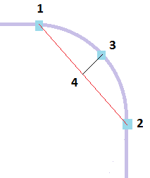
The edge length for the beams in that section of the curve is calculated so that the resulting ratio falls into the allowable range. |
| Minimum number of elements on each curve for gates | Material entering the cavity is a critical phase of the injection molding process. It is recommended that the sections of the curve that represents the gates should be modeled with at least 2 beam elements. This is the default value for this parameter which can be adjusted in integer steps between 1 and 5. |
| Minimum number of elements on each curve for baffles and bubblers |
This value corresponds to the minimum number of beams elements that need to be created on the sections of the curve that represents the baffles and bubblers. 3 beam elements is the default and minimum value, and can be adjusted in integer steps between 3 and 50.
|
CAD tab
Allows you to set mesh parameters for CAD entities.
| Widget | Explanation |
|---|---|
| Use auto sizing | Check this option to automatically set the edge length and chord angle based on the dimensions and curvature.
Note: The global edge length defined in the
General Tab do not apply when this option is checked.
|
| Scale factor | Allows you to adjust the size of the mesh elements generated with the Use auto sizing by applying a scale factor. |
| Use global parameters | Check to use the global edge length defined in the General Tab. |
| Chord Angle | When selected, you can control the mesh density of curved features of the model by defining a chord angle. |
| Contact interfaces | There are three options that can be used for meshing assembly contact faces.
|
NURBS tab
Allows you to match a Dual Domain mesh or smooth a Midplane mesh to assist post-processing after analyzing the model.
| Widget | Explanation |
|---|---|
| NURBS surface mesher | Specifies which meshing technique should be used to generate the mesh on imported Non-uniform Rational B-Splines (NURBS) surfaces.
The following options are available:
|
| Enable chord height control | Increases the chance of creating a mesh that closely corresponds to curved surfaces.
Without chord height control, some surface curves, such as fillets, degrade when meshed. Chord height control is effective only with parts that have curved surfaces. Tip:
|
| Optimize aspect ratio by surface curvature control | Adjusts the size of the mesh to the local curvature on NURBS surfaces automatically. |
| Optimize aspect ratio by proximity control | Detects proximities between boundary curves automatically, and ensures adequate mesh refinement at locations where boundaries are close to one another. |
| Smooth mesh (NURBS surfaces only) | Allows you to smooth the edges of a Midplane mesh. |
| Merge tolerance | Sets the minimum distance between nodes that will be targeted when generating the mesh.
If adjacent nodes are closer together than this distance, these nodes will be merged together during mesh creation. |
Tetra tab
Sets the minimum number of elements and maximum aspect ratio that Autodesk Moldflow Insight uses to generate the 3D mesh.
| Widget | Explanation |
|---|---|
| 3D Mesher | Specifies which meshing technique should be used to generate the tetrahedral mesh.
The following options are available:
|
| Minimum number of elements through the thickness | Sets the minimum number of elements through the thickness that is targeted when generating a 3D mesh.
Tip: Increasing the number of elements through the thickness increases the total number elements, which increases computation time. Despite increased computation time, it can be worthwhile to increase the minimum number of elements if you have a very thin part and you need an improved temperature solution. Check that the resultant Aspect Ratios are acceptable and decrease the
Global edge length on surface if necessary.
|
| Ratio of maximum tetra edge length in thickness direction to global edge length | When the global edge length is altered, the maximum tetra edge length is automatically adjusted to maintain the required ratio.
It is advised to use a ratio between 0.4 and 1.5.
Note: This option is available for
Advancing Front 3D mesher only.
|
| Ratio of edge length in thickness direction near surface to global edge length | This ratio is available for Advancing Layers 3D mesher only and set to .5 by default. |
| Tetra aspect ratio control | Allows both automatic ratio control and a manual setting for maximum allowed aspect ratio.
|
Tetra Advanced tab
Moves and distributes nodes in order to reduce the aspect ratio of generated tetrahedral elements when generating a 3D mesh from a Dual Domain mesh.
| Widget | Explanation |
|---|---|
| Use surface mesh optimization | Creates a mesh with fewer high aspect ratio elements. This option is on by default and should only be deselected if the quality of the surface mesh suffers. |
| Use surface mesh matching | Specifies that a uniform volume mesh is created, aligned through the thickness with the elements on the top and bottom of the surface initial Dual Domain mesh. For very chunky parts, there is often little value in matching the Dual Domain surface mesh. For these parts, deselect this option and a 3D mesh is generated with a different algorithm that does not rely on the surface mesh. |
| Node biasing through thickness | Allows you to adjust the relative thickness of each element layer in a 3D part. This is achieved by shifting the node layer closer to either the surface or the center of the part.
When node biasing is applied, the number of element layers and nodes through a part's thickness is still the same, but the local thickness of each layer will be changed.
|
| Mesh smoothing | Select how existing nodes should be distributed in order to smooth the mesh.
|