This panel is used to define and create a finite-element 3D mesh for a mold imported into, or created in Autodesk Moldflow Insight .
Not all tabs are visible all of the time. Different tabs will be visible depending on how you have generated your mold.
General settings
| Mesh Now | Starts the mesher |
| Job Manager | Opens the Job Manager dialog so you can monitor the tasks |
Surface tab (only when generating a surface mesh for a Mold Surface)
| External mold surface edge length: | Specify a target value for the mold mesh external element edge length. Default: 3.6mm |
| Internal mold surface edge length: | Specify a target value for the mold mesh internal element edge length. Default: 1.8mm |
| Check contact interfaces between internal bodies | Make sure this box is checked if you have mold inserts, part inserts or cores, to ensure that the contact interfaces between all internal components are checked, prior to meshing the mold. |
General tab (only when creating the 3D mold mesh)
| Global edge length on surface | Specify a target value for the mold mesh element edge length. Default: 1.8mm |
Tetra tab
| Minimum number of layers between external and internal mold surfaces | Specify the minimum number of layers you would like through the mold. The more layers you specify, the more accurate the temperature, but the longer the analysis will take. Default: 6 |
| Mesh size gradation ratio from internal to external surfaces | Specify the change in size of the mesh as a ratio, from the coarser (larger mesh) outside surface, to the finer (smaller mesh) inside surface. Default: 1.5 |
| Maximum allowed edge length through thickness near external surface (Mold Surface wizard only) | Specify the maximum edge length near the external mold surface, to determine the coarseness of the mold mesh. The mesh size will gradually change from this value to the value specified for the edge length near the internal mold surface. |
| Maximum allowed edge length through thickness near internal surface (Mold Surface wizard only) | Specify the maximum edge length near the internal mold surface. This value should always be less than or equal to the edge length at the external mold surface. |
| Maximum allowed edge length through thickness (CAD/STL mold only) | Specify the maximum edge length through the mold, to determine the coarseness of the mold mesh. |
Note: Any mesh option marked with * can be saved as part of a workspace default.
Curves tab
| Edge length vs. diameter for circuits | The ratio of edge length to cooling circuit diameter is used for beams with a property of Circuits. Values for this ratio must fall between 0.5 and 8.0 with the default value of 2.5 |
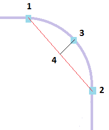
| Maximum allowed chord height vs. chord length | Straight beams are used to emulate a curve that turns, for example, through 90 degrees. Applying an edge length that is suitable for the straight sections of a feed system, could result in an inaccurate representation of the turn.
To allow ensure an appropriate edge length is applied, the cord height (distance 3 to 4 in the following diagram) is divided by the chord length (distance 1 to 2). The default value for this ratio is 0.05 with an available range of 0.02 to 0.3. Shortening the edge length will reduce the chord height and so reduce this ratio.
|