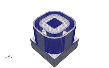
Part-Level Powder-Bed modeling involves activating elements in groups of layers. The feature is triggered by the *PBPA card and requires adaptivity (*ADAP), substrate definition (*DDM!), and Process Parameter File (*PBPF) cards. Each layer group is activated at a fine element scale, as additional layers are deposited on the top, elements below are coarsened. The figures below show the mesh during activation of the 72nd and 91st layer groups.
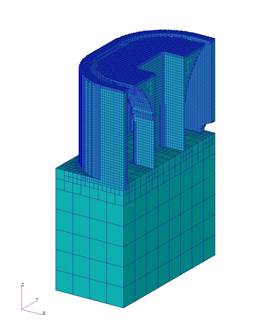
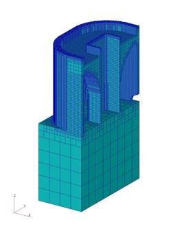
Mesh after activation of 72nd layer group Mesh after activation of 91st layer group
Part-Level Powder-Bed modeling involves both a thermal and a mechanical analysis. Currently, the powder is removed from the mesh and heat loss into the powder is modeled as convection *CONV. The mechanical analysis uses the temperatures computed from the thermal analysis to compute the mechanical response. The process parameters for part scale modeling are stored in a separate file and read using *PBPF.
In Part-Level Powder-Bed modeling, the input mesh can be automatically generated by importing an STL file using *STLF. When the *STLF option is used, information entered in the *DDM! Card is used to determine the thickness of the buildplate.
Substrate preheating for *PBPA analyses is modeled by using the *INIT card in the thermal analysis only. Continuous controlled heating of the substrate is modeled by the *PBSH and *INIT cards in the thermal analysis only. When substrate preheating or continuous heating is modeled, *INIT in the mechanical analyses should be set to room temperature. The *PBSS card can be used in the mechanical analysis to prevent the substrate from bulging. The *PBIS card can be used to insulate the sides of the substrate during thermal analyses, essentially simulating a build plate withmany different builds. By default the substrate size is small, only extending to the bounds of the .stl box. However, if the user wishes to use a larger substrate the dimensions can be extended using *SBDM or *SBXY. Circular or rectangular fixtures can be added to the substrate using *FIXC and *FIXR, respectively.
*PBPA: Powder-Bed Part-Level Analysis
*PBPA
il
i1: i*4: number of layers grouped per element.
This card controls the number of layers combined to form the smallest element thickness. If the deposited layers in the source PRM simulation have a thickness t then the smallest elements will have sides il*t in length. The minimum *PBPA value allowed is 5.
Best Practices: il*t should never be larger than half of the width of the thinnest wall in the structure being modeled. However, this is not always feasible. Using the GUI to generate input files will perform these calculations automatically. Using larger values of *PBPA will dramatically increase the speed of simulations, so the largest value possible should always be used. Good engineering practice dictates a 3-part mesh convergence study with respect to displacements should always be performed by the user for each new geometry.
One can see in the first figure below that using *PBPA values that are too high will not preserve the geometry of the reference .stl file. As the *PBPA values are decreased (subsequent figures) geometry is preserved, but the mesh may be too coarse to resolve the solution accurately. As *PBPA moves towards the limiting value of 5, the solution converges. However, reducing *PBPA comes at the cost of increasing run times. Looking at the converged solution for the *PBPA = 10 and 5, the single core run time increases by 6 times.
*PBPA=125, Thermo-mechanical run time = 3.12 s
*PBPA=25, Thermo-mechanical run time = 43.9 s
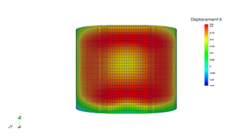
*PBPA=10, Thermo-mechanical run time = 43.9 s

*PBPA = 5
*PBPF: Powder-Bed Parameter File
*PBPF
a1
a1: a30: Process Parameter file prefix
All Part-Level Powder-Bed analyses require a process parameter file as an input. This card allows the user to select the desired file.
From V.288.14 onward, multiple PRM files may be input when using multiple STL files, which are input using *STLF and assigned PRM files using *STLM.
*+PDR
*+PDR
This card introduces powder elements into the part-scale powder-bed modeling. This must be used in both the thermal and mechanical analysis files. This allows for more accurate predictions of heat transfer during powder bed simulations. By default powder material properties are scaled so that the thermal conductivity is 0.01X solid part conductivity, and powder specific heat is 0.60X solid part specific heat. Scaling can be controlled using *DDM1 or the powder can be assigned its own material properties directly using *DDMM in conjunction with the material property card, *MATI. When using this card the powder elements will be visible in the thermal analysis. This is of particular interest when modeling parts that trap powder within their body, multiple parts on a build plate that are close enough to transfer heat amongst the various parts, or a part with disparate sections that may transfer heat back to itself through the powder. Note that the powder elements will not be displayed in the mechanical simulation, as the powder elements are not attached to the body, and will have no effect upon the mechanical behavior.
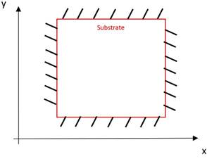
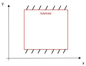
*PBIS: Powder-Bed Insulted Substrate
*PBIS
This card turns on insulating sides and bottom of the build plate in *PBPA analyses. The figure below illustrates the condition.
Surfaces insulated by *PBIS
*PBSH: Powder-Bed Controlled Substrate Heating
*PBSH
r1
r1: r*8: Substrate temperature
This card fixes the bottom side of the substrate to a temperature r1 in *PBPA analyses. This option represents the condition when controlled heating is used to maintain the build plate at a desired temperature.
*PBS2: Powder-Bed Substrate Material ID 2
*PBS2
This card assigns and uses material ID 2 for the build plate, allowing the user to make the build plate a different material than the deposited metal. If *PBS2 is not used, both the build plate and the part are assigned material ID 1.
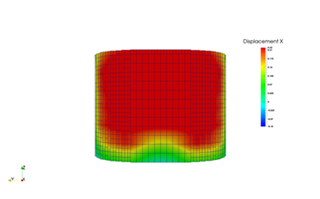
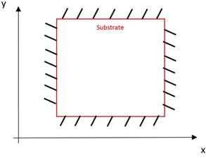
*PBSS: Powder-Bed Symmetry BC's on Sides of Substrate
*PBSS
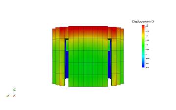
The figure below illustrates the effect of this option. This card turns on symmetry boundary conditions (displacement only) on the sides of the substrate when *STLF is used in *PBPA analyses. This card also turns on symmetry boundary conditions (displacement and heat ux) on the sides of the part when *LSRP is used in *AUTM analyses.
Surfaces constrained by *PBSS
*PBSX: Powder-Bed Symmetry BC's on Sides of Substrate
*PBSX
This card also turns on symmetry boundary conditions (displacement and heat flux) on the X axis sides of the part when *LSRP is used in *AUTM analyses. This option represents deposition of finite thickness sections. The option is illustrated in the figure below.
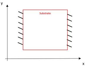
BCs assigned by *PBSX
*PBSY: Powder-Bed Symmetry BC's on Sides of Substrate
*PBSY
This card also turns on symmetry boundary conditions on the Y axis sides of the part when *LSRP is used in *AUTM analyses. This option represents deposition of finite thickness sections. The option is illustrated in the figure below.
BCs assigned by *PBSY
*FSUB: Floating SUBstrate
*FSUB
This card applies displacement boundary conditions on the substrate of part scale powder-bed analyses to simulate rigid fixturing during deposition and release from the machine during cool down.
The figure below depicts the use of the *FSUB card. During deposition only the z coordinate at the bottom side of the substrate is fixed and the x and are free, except for a circular region at the center of substrate with a radius equal to the largest element size. During the cooling time increment, the z coordinate is released to simulate removal of the substrate from the machine. When the *FSUB card is used, the *PBSS card is ignored.
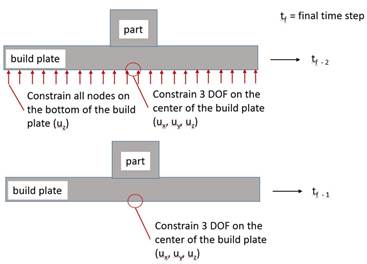
BCs assigned by *FSUB
*STLF: STL File
*STLF
a1
a2
a3
....
a1: a*80: STL file name
This card is used for Powder-Bed Part-Level analyses and allows the user to select an STL file to use. The mesh will be automatically generated from the file.
From V2.88.14 onward, multiple STL files can be imported using this card. Assign material properties and structure type using *STLM. Set the gap tolerance using *STOL. If there are overlaps between the STL files then they are meshed by order of listing.
*STLM: Multiple STL Mapping
*STLM
i1, i2, i3, r1
i5, i6, i7, r2
...
i1, i5: i*4: Configuration id: 1=part, 3= support structure
i2, i6: i*4: PRM number
i3, i7: i*4: Material ID number
r1, t2: r*8: Volume fraction
This card assigns structure type, PRM file, material id, and volume fraction. The configuration id number specifies what type of body the imported STL is, build part or support structure. The PRM number allows multiple PRM files to be used, which allows for modeling using different parameters on different parts. This number should correspond to the location in the list provided in *PBPF. The material id set the material properties for each STL component using the values in *MATI. The volume fraction is used to scale properties for support structure STL files, using a value of 0 to 1. Volume fraction should always be set to 1 for part files. For support structure STL files, adjust the volume fraction so that it matches the ratio of support material volume to the total volume that the support structure occupies.
*STOL: multiple STL Tolerance
*STOL
r1
r1: r*8: Multiple STL gap tolerance
The card is used to prevent holes between parts when using multiple STL files. It should be assigned in the native STL units (e.g. mm, in, m, etc.). This value will expand each STL by the value chosen, r1, so it is best practice to make this as small as possible, without producing any holes. If overlap occurs, the mesh is assigned to the value in *STLM via the order of listing in *STLF.
*STLS: STL File Scaling
*STLS
r1
r1: r*8: STL file scaling factor
This option is used to make the STL file units consistent with other analysis inputs. For example if the STL file is in inches, and the model properties are in mm, r1 should be 25.4.
*OSTL: Old STL Algorithm Switch
*OSTL
Version 2.81 of Local Simulation introduced a new, more efficient auto mesh generator. The option will revert the auto mesh algorithm used in versions prior to 2.81.
*RCTR: ReCoaTeR Tolerance
*RCTR
r1
r1: r*8: Recoater tolerance in %. Default 20%.
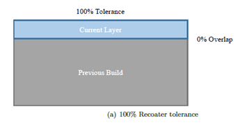
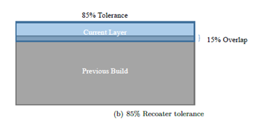
If the thickness of the powder layer is reduced due to distortion below r1% of the nominal layer thickness, a warning message is generated signaling a possible interference between the recoater blade and the build. Think of tolerance as a measure of clearance between the previous build and the recoater blade.
The figures below help illustrate how recoater tolerance is calculated. In Figure a, there is 0.040 mm allocated for the fusion of the next layer, and there is 0.40 mm on top of the build, which results in a 100% tolerance or clearance.
In Figure b, distortion of the previous build has taken up 0.006 mm or 15% of the tolerance, which results in 85% of tolerance remaining. This would be acceptable if your recoater tolerance was set to the default value of 20%.
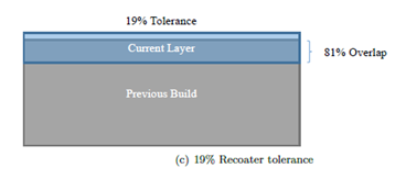
In Figure c, there is a 0.0321 mm build overlap, taking up 81% of the tolerance, resulting in only 19% recoater tolerance remaining and a warning message, as the tolerance is below the threshold of 20%.
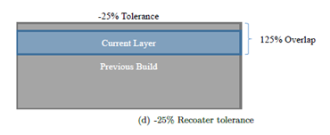
In Figure d, the build of 0.050 mm exceeds the entire recoater clearance of 0.040 mm for the current layer, so it returns a warning and a calculated interference of -25%. This loss of tolerance would almost certainly result in recoater blade damage.
A new feature (from V.287.17 on) is the automatic writing of the a new text file, file_name??? recoater.txt. This file records the time, layer group number, recoater clearance %, peak height of the deformed model at the top of the layer group, and the nominal recoater height at the top of the layer group. A sample file is shown below:
time (s), layer group, recoater clearance (%), top z deformed coord (mm), recoater coord (mm)
9.024533E+03           1      93.331     1.602668E+00     1.640000E+00
1.805244E+04           2      89.961     3.204015E+00     3.240000E+00
2.712766E+04           3      76.513     4.809395E+00     4.840000E+00
3.624973E+04           4      72.380     6.411048E+00     6.440000E+00
4.540336E+04           5      73.722     8.010511E+00     8.040000E+00
5.457021E+04           6      78.515     9.608594E+00     9.640000E+00
6.375136E+04           7      80.608     1.120776E+01     1.124000E+01
7.295711E+04           8      82.051     1.280718E+01     1.284000E+01
8.221741E+04           9      74.441     1.441022E+01     1.444000E+01
9.153668E+04           10     69.227     1.601231E+01     1.604000E+01
1.010004E+05           11     -1.821     1.764073E+01     1.764000E+01
1.106051E+05           12    -24.325     1.924973E+01     1.924000E+01
1.204665E+05           13      0.818     2.083967E+01     2.084000E+01
1.308714E+05           14      7.291     2.243708E+01     2.244000E+01
1.414172E+05           15      4.956     2.403802E+01     2.404000E+01
1.519087E+05           16     -4.642     2.564186E+01     2.564000E+01
1.624634E+05           17     -1.487     2.724059E+01     2.724000E+01
1.728352E+05           18     -2.322     2.884093E+01     2.884000E+01
1.830612E+05           19      8.865     3.043645E+01     3.044000E+01
1.932244E+05           20      6.861     3.203726E+01     3.204000E+01
2.032568E+05           21      4.110     3.363836E+01     3.364000E+01
2.133567E+05           22      2.824     3.523887E+01     3.524000E+01
2.229929E+05           23     -9.362     3.684374E+01     3.684000E+01
This example file shows that recoater interference is almost certainly going to be a problem for this build, starting from layer 11 onward. This is another feature to help guide the end user towards adding or strengthening support structures, changing building parameters, orientation, or part geometry to ensure that a useful part can be printed.
*PBCH: Powder Bed CHech Matrix Size
*PBCH
This card turns on check run or the sparse matrix pre-processing (auxspar) for the entire build mesh at the beginning of the analysis. This feature is useful in calculating the biggest stiffness matrix size before the entire analysis is run.
*PBDL: Powder Bed DwelL Time
*PBDL
r1
r1: r*8: number of parts on build plate.
This option automatically calculates, based on the layer volume, the amount of time that it takes to deposit layers in powder-bed processing. The time is added into part scale analyses to allow for the calculation of actual cooling periods. The time is calculated using the following equation:

where t is the added processing time, V is the volume of the added material calculated from the part geometry, v the laser speed, h is the hatch spacing, and d is a single powder layer thickness. Adjusting r1 accounts for the case where a user is simulating fewer parts than what will appear on the actual build plate. For example, if 4 similar parts will be on the actual build plate and the user wishes to simulate the build using an .stl file that contains only 2 of the parts, r1 should be set to 2. This will double the analysis deposition times.
*PBLR: Powder Bed Layer Refinement
*PBLR
i1
i1: i*4: number of generations coarsened per activation layer. Default 1.
This option allows using small element size (defined by *PBPA) to account for fine geometry details or thin sections, and activating layers thicker than the finest element size.
The activation thickness is equal to n · t · 2i1, where n is the number of layers per group and t is the powder layer thickness (i2 and r1 values in *PBPA card). The effect of the *PBLR card is illustrated in the figures below, where in Figure a it is shown that the added group of elements is composed of fine elements without the *PBLR card. The adaptive coarsening allowed by *PBLR is shown in Figures b and c. Note that single core run times can be quartered between the No *PBLR and *PBLR = 2 simulations, however this coarsening will reduce the accuracy of the simulation.
Best Practices: *PBLR = 1 should achieve a fair compromise between speed and accuracy for most geometries. Larger geometries should use values of *PBLR = 2, extremely large builds,*PBLR = 3. Good FE practice requires a mesh convergence study for each model.
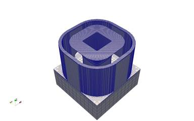
(a) No *PBLR, *PBPA = 5, Run time = 13965 s
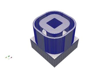
(b) *PBLR = 1,*PBPA = 5, Run time = 6462 s
(c) *PBLR = 2,*PBPA = 5, Run time = 3213 s
*GTAB: Generate Tables
*GTAB
This option allows the user to output a process parameter (PRM) file from a moving source analysis.
This .prm file is required to run Part-Level Powder-Bed analyses.
This option must be used in both the thermal and mechanical analysis when generating PRM files. To get accurate PRM files, you must run the simulations using the prm_gen command.
*NAPL: Use New Method for *GTAB Analyses
*NAPL
This card directs the code to use a new method for *GTAB analyses. The old method was stretching free faces of the modes to zero out-of-plane displacement at the last time increment. When *NAPL is used, the faces remain free.
Required Cards: *GTAB
*HPRM: Hidden process PaRaMeters
*HPRM
This card turns off the default option that outputs the processing parameters in log files, which can be used to protect proprietary processing parameters.
*HMAT: Hidden MATerial Properties
*HMAT
From version V.2.89 onward, material properties are written by default into the PRM file. These are then read by the solver during Part Scale analysis, so material properties no longer have to be specified again in the part scale input files. The material properties used are written to the output file during part scale simulations. Using the *HMAT card will prevent properties from being written to the output file.