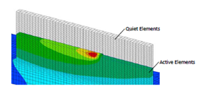
Elements used in the analysis can exist in the following three states:
- Active elements – included in the analysis and given their true material properties.
- Quiet elements – included in the analysis but are given material properties such that they do not affect the simulation. For thermal simulations the thermal conductivity and specific heat are scaled down. For mechanical analyses the elastic modulus is scaled down.
- Inactive elements – not included in the analysis.
(Reference: P Michaleris. Modeling Metal Deposition in Heat Transfer Analyses of Additive Manufacturing Processes. Finite Elem in Analysis and Design, 86:51-60, 2014.)
Element activation
*DDM!: Automated Activation by Layer Using Hybrid Inactive/Quiet Method
*DDM!
r1, r2, [r3]
r1: r*8: top z coordinate of substrate
r2: r*8: bottom z coordinate of substrate
r3: r*8: time offset to activate layers, in seconds. Default radius/velocity/4
This DDM option switches elements from inactive to quiet on a layer by layer basis. The time of layer activation is set to the start of deposition of each layer minus r3. Then, Local Simulation searches which elements belong to each layer based on their z coordinate. The elements are activated when contacted by the heat source.
For auto-generated meshes, this card also defines the substrate or build plate thickness. r1 should correspond to the bottom coordinate of the .stl file or the heat source path and r2 defines the thickness of the auto generated substrate.
*DDM1: Parameter Definition for DDM Methods
*DDM1
r1, r2, r3, [r4]
r1: r*8: scaling factor for thermal conductivity. Default 1.d-6
r2: r*8: scaling factor for specific heat. Default 1.d-2
r3: r*8: scaling factor for elastic modulus. Default 1.d-4
r4: r*8: scaling factor for emissivity. Default 1.d0
This option allows the definition of the scaling factors used for quiet elements.
Required Cards: *DDM!
*DDMC: Option to Define Clamp in Conjunction with *DDM!
*DDMC
i1
i1: i*4: Configuration ID of build elements
This DDM option is used in conjunction with *DDM! to differentiate the build areas of the mesh above or below the substrate from fixturing and clamps.
This DDM option can also be used in conjunction with *ADAP to define areas of the base mesh that do not need to be processed for adaptivity. These elements will not be refined.
Required Cards: *DDM!, *ADAP
*DDMM: Option to Define Mat ID for Quiet or Powder Elements
*DDMM
i1
i1: i*4: Material ID of quiet or powder elements
This option allows for use of a material ID to define the material properties of quiet or powder elements. When used, quiet elements are assigned this material ID initially. After the elements are switched to active, the element material ID is switched to that of the solid material. When *DDMM is used, no scaling of properties is used for quiet elements (Values defined by *DDM1 are ignored).
Currently implemented for thermal analysis only.
Required Cards: *DDM!
*DDMP: Switch for Powder-Bed Modeling
*DDMP
The option should be used when powder elements are present and has the following effects:
- The temperature of the quiet elements is not reset to the initial temperature upon their activation.
- Layers contain all elements, even those not activated as the powder is always included in the analysis, unlike direct processes, where the material is added.
Required Cards: Use *DDM1 or *DDMM to define powder properties and *DDM! to define element activation.
*DDMZ: Z Direction Element Floating
*DDMZ
This option allows elements to float in the Z direction during the mechanical simulation. This enables the modeling of direct processes (e.g. LENS and Electron Beam or Laser Direct Energy Deposition) using the multi-scale modeling approach.
*ADAP: Adaptivity Switch
*ADAP
i1
i1: i*4: Levels of element refinement. No default value.
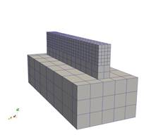
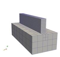
This option specifies the number of levels of element refinement for adaptive analyses in all three spatial dimensions. The maximum allowed value of i1 is 6. Levels of refinement are demonstrated below.
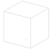
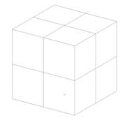
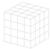
No refinement 1 level of refinement 2 levels of refinement
Unrefined mesh Refined with 2 levels of refinement Magnified refined mesh
Best Practices
Direct Energy Deposition or Moving Heat Source Powder Bed Simulations:
Using a Patran® generated mesh (using *INPU):
The Patran generated mesh will be the coarsest possible mesh as the adaptivity routines of Local Simulation will refine but not coarsen the mesh. Produce a mesh with 1-2 elements per laser radius in the laser path and at least 2 elements through the thickness of the substrate, using a combination of Patran, *ADAP, and *SUB2. Many, but not all, simulations will converge using 1 element per laser radius. Refinement beyond 2 elements per laser radius will prolong simulation times without giving more accurate thermo-mechanical simulations.
Using a Local Simulation generated mesh (using *AUTM):
The automatic mesh generation element size is based upon the laser radius size and *NELR (which has a default value of 1). Ensure there are 1-2 elements per laser radius in the laser path and at least 2 elements through the thickness of the substrate.
*ADAP values of 1-4 are typical.
Part Scale Powder Bed Simulations
Part scale meshes are generated from STL files. Meshing of the manufactured component is controlled by *PBPA and *PBLR, while *ADAP controls the coarsening of the substrate. Higher levels of adaptivity yield coarser build plate meshes. A value of 4-5 is adequate for most simulations.
*ADPM: Switch for Moving Element Coarsening/Refining Within Layer
*ADPM
r1
r1: r*8: Tolerance for element coarsening. Default 50.d0
This option turns on moving-source adaptivity and can only be used for moving heat source powder bed thermal analyses of a single layer. When the temperature gradient across an element equals r1 or below, the element will be eligible for coarsening.
Required Cards: This card requires the use of *DDMP and *LSRP.
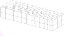
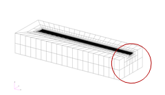
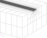
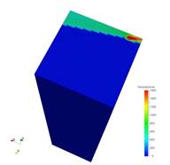
The effect of using *ADPM is shown in the figures below, along with the associated single CPU run times. Without using *ADPM, the mesh has excessive resolution to resolve the problem. Using the default value of 50 reduces simulation time by 82%. Changing the value of *ADPM to 100 generates a further reduction of run time of 31% over the default value. A similar reduction of time is achieved by using *ADPM of 1000, but note in the fourth figure that thermal aberrations occur. These are due to the improper integration of heat over the part.
Best Practices: The default value of 50 is a good compromise between speed and accuracy. *ADPM should not be set below 25.
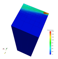
*ADPM = off, Run time = 3797 *ADPM = 50, Run time = 665
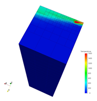
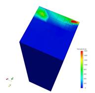
*ADPM = 100, Run time = 461 *ADPM = 1000, Run time = 306
*ADP1: Adaptive Refinement Control Parameters
*ADP1
i1
i1: i*4: Number of layers, minimum 2. Default 2.
This option controls the number of fine layers beneath the deposition layer when coarsening. The effect of this card is shown in the figures below, using values of 2, 5, and 10, including the single CPU runtime for each simulation.
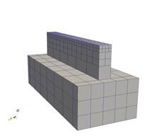
*ADP1 = 2, Run time = 27s *ADP1 = 5, Run time = 42s *ADP1 = 10, Run time = 66s
Required Cards: *ADAP
*ADP1 is used to refine layers below the deposition to preserve simulation information and to prevent over-coarsening of the mesh, which can result in an artificially high stiffness, diminishing the accuracy of the mechanical simulation. At a minimum there should be 2 elements through the thickness of the substrate throughout the simulation history, which may be achieved by using either *ADP1 or *SUB2.
*ADP2: Adaptive Relaxation Control Parameters
*ADP2
i1
i1: i*4: Number of relaxation iterations after refinement/coarsening in mechanical analysis, minimum 2. Default 5. Increase this number above 5 to aid mechanical simulations which fail to converge at increments when a new layer of elements is activated.
Required Cards: *ADAP
*ADP3: Adaptive Option to Define Element to be Refined
*ADP3
i1
i1: i*4: Configuration ID of build elements
This option is used in conjunction with *ADAP to define elements that will be refined. Elements with different configuration ID will not be refined. This can only be used in conjunction with a Patran-generated mesh, using *INPU.
Required Cards: *ADAP, *INPU.
*SUB2: SUBstrate Force 2 Element per Thickness
*SUB2
This card is used in combination with (*ADAP) to instruct the adaptivity algorithm to use at least 2 elements in the thickness direction of the substrate.
Required Cards: *ADAP
*AXSP: AuXSPar Array Size Scaling Factor
*AXSP
r1, r2
r1: r*8: Scaling factor for initial condensation array vector. Default 1 r2: r*8: Growth scaling factor for condensation array, Default 1.
This card is used to increase the maximum size of the condensation solution array. Adjusting r1 will increase the initial size of the matrix array. If this array is too small, the growth scaling factor multiplies the initial array size by 1.10*r2. This process is repeated until the array is large enough to contain the entirety of the condensation array.
This option should be used when the program exits during the auxspar phase of the program initialization, for extremely large or extremely fine meshes.
Best Practices: Use *AXSP only for simulations that do not complete the meshing step with the default parameters. Good initial values would be r1 = 1.1, r2 = 1.1.
*SYMM: SYMMetry Plane Definition for Adaptive Analysis
*SYMM
i1, r1
i2, r2
...
i1: i*4: normal to plane axis 1 for x, 2 for y, 3 for z
r1: r*8: coordinate of plane location
This option allows for the definition of symmetry planes in *ADAP mechanical analyses.
Required Cards: *ADAP