*COOL: Additional COOLing Step
*COOL
This card adds one more time increment in mechanical analyses to simulate cooling back to the initial part temperature. This option is automatically turned on when using *PBPA.
*AUTM: AUTo Mesh Generation
*AUTM
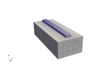
This card automatically generates an input mesh for moving source analyses, including PRM generation and direct process simulations.
For moving source powder-bed analyses, *LSRP and *DDM! specify model volume and thickness, respectively, while the mesh parameters are determined by *ADAP and *ADP1.
For direct processes, geometry is defined by the deposition volume in *LSRF and depth set by *DDM! and the mesh refinement is controlled by by *ADAP, *NELR, and *ADP1.
Additional substrate volume can be specified by extension via *SBXY or by specifying minimum and maximum X and Y coordinates using *SBDM. Substrate depth is also controlled via *DDM!.
*FIXC: FIXture Circular
*FIXC
r11, r12, r13
r21, r22, r23
.... r11: r*8: Radius r12: r*8: x-coordinate r13: r*8: y-coordinate
This card is used in conjunction with *AUTM, or *STLF to define the circular fixtures on the bottom of the build plate. All nodes within the defined circles are fixed in all 3 axes. The following figure illustrates the option.
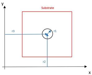
Positioning of a circular constraint
Best Practices: Use *FIxR if practical to avoid overconstraining the part.
*FIXR: FIXture Rectangular
*FIXR
r11, r12, r13, r14
r21, r22, r23, r24
....
r11: r*8: min x-coordinate r12: r*8: max x-coordinate r13: r*8: min y-coordinate r14: r*8: max y-coordinate
This card is used in conjunction with *AUTM, or *STLF to define the rectangular fixtures on the bottom of the substrate. All nodes within the defined rectangles are fixed in all 3 axes. The following figure illustrates the option.
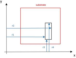
Positioning of a rectangular constraint
Best Practices: Use *FIxR if practical to avoid overconstraining the part.
*FIxR: FIxture Rectangular
*FIxR
r11, r12, r13, r14, i11, i12, i13, i14
r21, r22, r23, r24, i21, i22, i23, i24
....
r11: r*8: min x-coordinate r12: r*8: max x-coordinate r13: r*8: min y-coordinate r14: r*8: max y-coordinate i11: i*4: x-coordinate [0 for free, 1 for fixed] i12: i*4: y-coordinate [0 for free, 1 for fixed] i13: i*4: z-coordinate [0 for free, 1 for fixed] i14: i*4: load case number
This card is similar to *FIXR and *FIXC. However, it offers more flexibility to specify which degree of freedom is fixed. It also allows specification of load case number.
Best Practices: Using *FIxR allows for greater control than *FIXR and *FIXC and is less prone to overconstrain the part, which may produce erroneous results. Ensure that when using *FIxR 6 degrees of freedom (DOF) are restrained. Fewer than 6 restrained DOF will allow bulk motion of the component during simulation while using more than 6 DOF will overconstrain the part, which may incur erroneous simulations of distortion and stress. As of this version there is no warning given when under or over constraining the simulated part.
*FISR: FIxture Spring Rectangular
*FISR
r11, r12, r13, r14, i11, i12, i13, i14, i15
r21, r22, r23, r24, i21, i22, i23, i24, i25
....
r11: r*8: min x-coordinate r12: r*8: max x-coordinate r13: r*8: min y-coordinate r14: r*8: max y-coordinate i11: i*4: x-coordinate [0 for free, 1 to add spring] i12: i*4: y-coordinate [0 for free, 1 to add spring] i13: i*4: z-coordinate [0 for free, 1 to add spring] i14: i*4: material ID i15: i*4: load case number
This card is similar to *FIxR. However, instead of fixing degrees of freedom, it adds nonlinear springs at specified degrees of freedom. The stiffness of the spring is defined using the *DASH card.
*NELR: Number of ELements per Radius
*NELR
r1
r1: r1*4: Number of element per melt pool radius. Default 1.
This card is used in conjunction with *AUTM and *ADAP to define the number of elements per melt pool radius in all three planes. Integer or real values are accepted.
The following figures illustrate the effect of *NELR card upon the auto-generated mesh. Note that the change in elements per laser radius will scale up the total number of elements in the model. It is recommended to increase the *ADAPT value to inhibit extraneous element production.
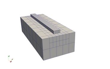
(a) NELR = 2, *ADAP = 2
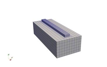
(b) NELR = 4, *ADAP = 2
(c) NELR = 4, *ADAP = 3
*PARL: Parallel Activation Element Number
*PARL
i1
i1: number of elements in mesh above which parallel execution is turned on. Default 500
*SBXY: SuBstrate XY extentions
*SBXY
r1, r2, r3, r4
r1: r*8: x1-extension r2: r*8: x2-extension r3: r*8: y1-extension r4: r*8: y2-extension
This card is used in conjunction with *AUTM, or *STLF to define an extension of the substrate beyond the bounding box of the part. The following figure illustrates the option.
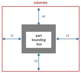
Assigning substrate geometry using *SBXY
*SBDM: SuBstrate DiMensions
*SBDM
r1, r2, r3, r4
r1: r*8: min x-coordinate r2: r*8: max x-coordinate r3: r*8: min y-coordinate r4: r*8: max y-coordinate
This card is used in conjunction with *AUTM, or *STLF to define the XY coordinates of the substrate beyond the bounding box of the part. The following figure illustrates the option.
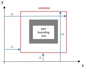
Assigning substrate geometry using *SBDM
*BOXM: Bounding BoX Mesh Output
*BOXM
This card turns on write output of bounding box base meshes (showing the size of the substrate prior to deposition) for moving source analyses with auto mesh generation, to a file called ???_geom.case in the simulation directory, where ??? is the extensionless input file name.