*CLIF: CLI File
*CLIF
a1
a1: a80: Name of CLI file
This card inputs the support structure CLI into the model. This automatically adds an additional iteration at the end of the simulation which removes the support structure from the model mesh. If portions of the CLI model overlap with the STL model, Local Simulation considers the co-located volume as fully dense. This card must be applied in both the thermal and mechanical input files when using support structures in the model. At this time only box type supports can be used in the model.
The following figures show examples of compatible box type supports, and an example layer slice of the supports. These can be easily generated using Netfabb with the provided automated support script box_type_no_fragments.support.
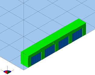
Box type supports on STL
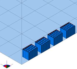
Box type supports
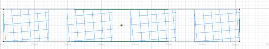
Box type layer slice
*VCLI: Volume of CLI
*VCLI
r1
r1: Volume fraction threshold for CLI files
This card sets the volume fraction threshold for activation of CLI generated elements. The volume fraction is the ratio of the volume of the elements in the mesh to the volume fraction of the source CLI. Elements with volume fractions lower than the threshold are not activated. The default value is 0.05.
Required Cards: *CLIF
*UTSR: Ultimate Tensile StRess
*UTSR
r1
r1: Tensile stress of support material
This card is used to simulate support structure failure during powder bed processing. This card specifies the ultimate stress of the support material input by *CLIF, within the *MATE card block for the build material properties. When the Z component of stress at the support-build interface exceeds the specified ultimate tensile stress, the element fails, producing a warning in the output file. A failed element remains in the mesh but does not resist deformation. An example of failed elements is shown in the following figure.
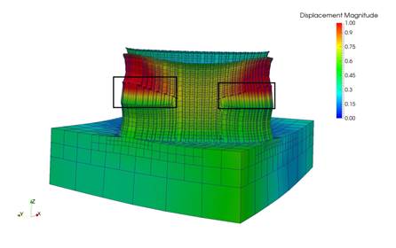
Example of failed elements using *UTSR, 5X magnification