*AMBI: Ambient Temperature
*AMBI
r1
This option sets the ambient temperature for thermal and mechanical analyses in oC.
*AUBC: Automatic Boundary Conditions Switch
*AUBC
This option can be used in conjunction with *ADAP for manually generated meshes using *INPU. Boundary conditions are automatically applied to all automatically generated (using *AUTM) meshes.
When *AUBC is used, the surface convection defined by the *CONV and the energy defined by the *LSRF card is used without boundary condition definition in PATRAN.
Required Cards: *INPU
*CONV: Convection Coefficients
*CONV
r11, r12
r21, r22
...
r11: r*8: Convection at temperature r12
r21: r*8: Convection at temperature r22
...
This allows for the definition of a temperature dependent convection in W/mm2 oC for temperatures specified in oC. Convection is automatically applied to the free surfaces of *AUTM auto-generated meshes. These values are also used at the interface of quiet and active elements (unless *DDMP is turned on).
*GOLD: Values for Goldak's Model
Reference: John Goldak, Aditya Chakravarti, and Malcolm Bibby. A new finite element model for welding heat sources. Metallurgical transactions B, 15(2):299-305, 1984.
*GOLD
r1, r2, r3, r4, r5, r6
The heat source definition is illustrated in the figure below.
r1: r*8: efficiency. Default 1.d0
r2: r*8: b axis multiplier. Default 1.d0
r3: r*8: c1 axis multiplier. Default 1.d0
r4: r*8: c2 axis multiplier. Default 4.d0
r5: r*8: f1 factor. Default .6d0
r6: r*8: f2 factor. Default 1.4d0
- The a axis dimension is set as the melt pool radius (typically about equal to the laser spot size) as defined in *LSRF
- r1 should be set to the absorption efficiency value.
- The b axis dimension is set as r2*a
- The c1 axis dimension is set as r3*a
- The c2 axis dimension is set as r4*a
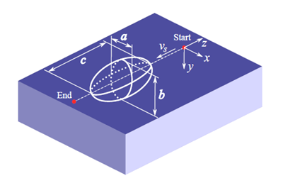
Schematic of the Goldak heat source
Best Practices: For moving-source powder bed, LENS® or other thin layer deposition, the b parameter, which controls the Z axis of the double ellipsoid volume of the heat input model, should be set to r2 = 0.6, which should give a fairly accurate representation of the melt pool, as described in Goldak’s article referenced above, and other modeling literature.
For thicker depositions, r2 should be adjusted so that the laser depth and layer height are identical, e.g.
r2 = layer height/laser radius
This is performed to ensure the entire deposition is melted. If there are unactivated elements or layers in the simulation results, check to see if the r2 value satisfies the above condition.
*3PLP: Improved Goldak Accuracy Card
*3PLP
Using this card will improve the accuracy of the Goldak heat input model. Use this card when using the simulation tool to investigate melt pool and related phenomena.
*LINQ: Line Heat Input (Q) Model
*LINQ
This option activates a line heat input model using an averaged heat source over a line. The length of the line is determined by the *TAUT card. For example, if for a value of 10 is specified by *TAUT, the length of the line is going to be 10 times the radius of the heat source as defined by the *LSRF card. When *LINQ is used, the content of *GOLD is still needed to compute the shape of the heat source distribution. Currently this option is only compatible with thermal analyses.
An illustration of the effect of using *LINQ is given in the following figure for the same simulation without using *LINQ (Figure a).
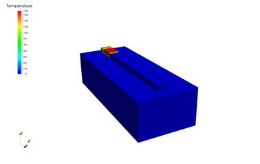
(a) *LINQ = off

(b) *LINQ = 5
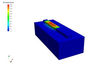
(c) *LINQ = 10
*GTOL: Tolerance Values for Source Heating Model
*GTOL
r1, r2
r1: r*8: line extension multiplier. Default 0.d0
r2: r*8: power tolerance. Default 1.d-10
r1 controls a small extension to the heating lines. If r1=1, heating starts c1 before the line start and ends after c2 after the line end (see *GOLD card).
r2 is a tolerance for element activation. If the power in a heating line is less than this value, elements are not activated. This value is useful when lines are added with zero power to model the moving forced cooling using the *LENS card when the laser power is off.
*INIT: INItial Temperature
*INIT
r1
r1: r*8: initial temperature value
This card defines the initial temperature for both thermal and mechanical analyses, in oC. If *INIT is not defined, the ambient temperature defined by *AMBI is used as the initial temperature.
*FINT: FINal Temperature
*FINT
r1
r1: r*8: final temperature value
This temperature, in oC, is used in the extra cooling *COOL increment in mechanical analyses. If *FINT is not defined, the initial temperature defined by *INIT is used.
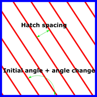
*LSRP: LaSeR Path Generation
*LSRP
r1, r2, r3, r4, r5, r6, i1, r7, r8, r9, [r10]
r1: r*8: power
r2: r*8 radius of melt pool
r3: r*8: travel speed
r4: r*8: layer thickness
r5: r*8: hatch spacing (gap width)
r6: r*8: deposition time from layer to layer
i1: i*4: number of layers
r7: r*8: initial vector angle
r8: r*8: vector angle change from layer to layer
r9: r*8: x width of part
r10: r*8: y width of part (if omitted set to r9)
This card generates a laser path for a rectangular patch with an area of r9 x r10. The path is stored as text file in <filename>.lsr, and used for the analysis. The value of the top substrate z coordinate is defined by the DDM! The laser path extends out of the part by a distance equal to the melt pool radius (r2).
Typically the radius of the melt pool (r2) is about twice the radius of the laser beam.
The figure below depicts an example schematic of the first two build layers using paths generated using *LSRP.
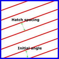
Layer 1
Layer 2
*LSRF: Moving heat source definition file
*LSRF
a1
a1: a*80: File name with content of laser lines
This option defines individual laser paths by reading a file, generated by the user, with the following format:
r11, r12, r13, r14, r15, r16, r17, r18, r19, r1(10), r1(11), r1(12), r1(13)
r21, r22, r23, r24, r25, r26, r27, r28, r29, r2(10), r2(11), r2(12), r2(13)
...
r11: r*8: power
r12, r13, r14: r*8: vector of heat source direction
r15, r16, r17: r*8: start point
r18, r19, r1(10): r*8: end point
r1(11): r*8: melt pool radius
r1(12): r*8: velocity
r1(13): r*8: start time
...
The heat source path is composed of linear segments.
*LENS: LENS Convection Values
*LENS
r1, r2, [r3]
r1: r*8: sphere radius. Default 0.d0
r2: r*8: local convection. Default 0.d0
r3: r*8: time gas is turned off. Default 1.d50
This card applies an additional component to the applied convection specified by *CONV in thermal analyses. This is used to simulate the forced convection due to the forced gas flows in the LENS process.
Reference: JC Heigel, P Michaleris, and EW Reutzel. Thermo-mechanical model development and validation of directed energy deposition additive manufacturing of ti-6al-4v. Additive Manufacturing, 2014.
*LENS models the region of forced convection as a sphere whose center is co-located with the center of the simulated heat source as controlled by *LSRF, of a radius r1 in mm, of a value r2 in W/mm2, which is cut off at time r3 in seconds.
A custom distribution of the forced convection can be programmed through the lensconvS subroutine in the user.f file.
*NELN: Maximum Number of Elements per Node
*NELN
i1
i1: i*4: Max number of elements per node. Default 20
This card is used to increase the max number of elements allowable per node in temporary pre-processing arrays. The card is needed in highly irregular meshes.
*RAMP: Ramping of Boundary Conditions
*RAMP
ID
i1, i2
r11, r12
r21, r22
... *ID
i1, i2
r11, r12
r21, r22
...
i1: r*4: boundary condition ID
i2: r*4: load case number
r11: r*8: multiplier at time r12
r21: r*8: multiplier at time r22
...
Boundary condition ID's:
6 element pressure
7 nodal force
8 nodal displacement
10 nodal temperature
15 nodal heat source
16 distributed heat source
17 convection
18 (radiation emissivity) not implemented
99 point (dash) elements)
For point elements (i1=99), i2 is the material ID of the element.
This card allows for boundary conditions to be scaled with respect to time.
*TAMB: Time-Dependent AMBient Temperature
*TAMB
r11, r12
r21, r22
...
r11: r*8: Ambient temperature value at time r12
r21: r*8: Ambient temperature value at time r22
...
When *TAMB is used, any values defined by *AMBI are ignored.
This option allows for the ambient temperate, in oC, during a thermal or mechanical analysis to be dependent on time, to simulate the change of temperature within a machine chamber during processing.