Open

Open a saved TIVUS file. The TIVUS file saves all the analysis settings and geometry files needed to run the simulation.
Import

Import 3D CAD files, or STL files, such as one exported from Netfabb, to provide the geometry for parts and support structures in a simulation. You can also import the results from a previously completed simulation in the form of a CASE file such as <part>_thermal.case or <part>_mechanical.case.
You can use multiple STL part and support structure files on a single build plate, but if you use a common layer interface (CLI) file for supports, only one such file is allowed.
When you import an STL file for a support structure, you can specify the volume fraction, which is the ratio of built material to the volumetric region that the supports occupy.
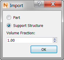
For example, if the volume fraction is 0.75, then 25% of the support volume is empty space.
About using PowerShape and Netfabb
If support structures are generated in Netfabb or PowerShape, volume fraction is automatically calculated. When pushing parts and support structures from PowerShape to the Simulation Utility we recommend that users create fixtures from the Tree type or Extrusion: solid. Both of these support types are approved for simulation. Other fixtures can be sent to the Simulation Utility, but may not be properly meshed and simulated.
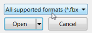
Simulation Utility supports more than 25 3D file types for the part model and the support structures. These are listed in the "Supported File Types" topic. In the Import model window, lower right corner, you can also click the ‘All supported formats’ list to see the supported format names and file extensions.
By default imported CLI structures are red.
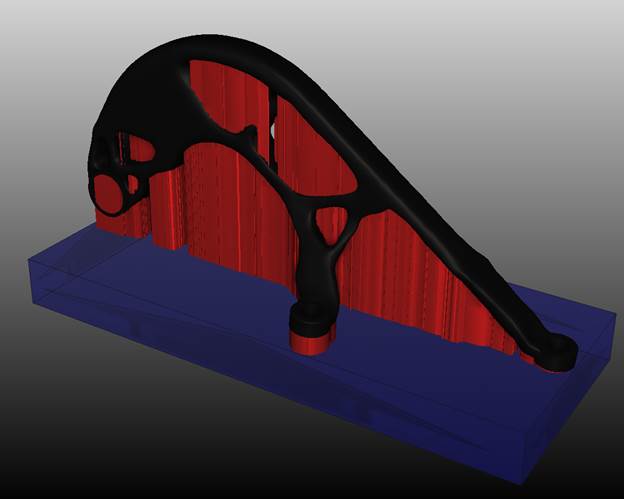
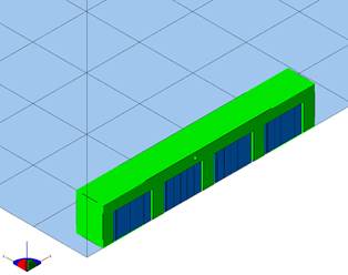
The figures below show examples of compatible box type supports and an example layer slice of the supports. These can be easily generated using Netfabb with the provided automated support script, box_type_no_fragments.support.
Box type supports on STL
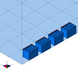
Box type supports
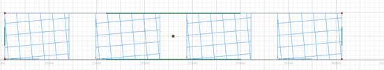
Box type layer slice
Save

Before running a simulation, click here to save your part file with the .tivus extension, specifying the name and location.
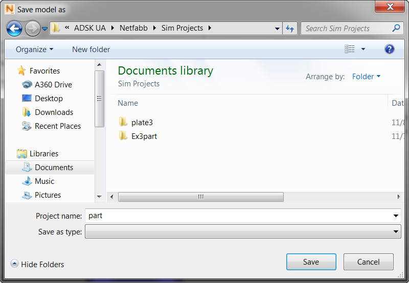
By default, the imported STL part name appears in the Project name field, and will be the name of the project folder, unless you decide to change it here. The model file (part.tivus in this example) is created inside the folder. When you run a simulation, related files will also be created inside the project folder. If you do not want to run the simulation now, you can do it later by clicking
Open
 and selecting the saved TIVUS file.