If one part is selected that contains self-intersections, you can also remove them in the slices. Or if two or more parts are selected, you can perform Boolean operations. Find both functions in the context menu in the submenu Extended. If one part is selected, you’ll find the Remove self-intersections button, if more parts are selected, the Boolean Operation button will be displayed instead.
 The Boolean Operation allows you to merge overlapping slices, create an intersection, or subtract one slice from the other. A dialog box appears in which the selected slice files can be assigned to the two fields Add and Subtract. At the beginning, all slices are in Add. If you click on a slice and then click on the arrow pointing to the other field, the file is moved there. If you click on the X, the selected file is removed.
To unify slices, all slices have to be in the left field Add. Execute the unification with the button Boolean. For an intersection of selected slices, choose Create Intersection in the context menu instead of Boolean Operation. The resulting slice includes only the overlap ping sections of all selected slices.
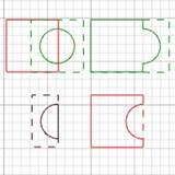
Top left: Two overlapping slices. Top right: A unification of those slices. Bottom left: The intersection of the slices. Bottom right: One slice is subtracted.

Left: Two overlapping slices. Center: Unify. Right: Intersection.
To subtract slices from others, you have to move those files you want to subtract into the right field in the dialog box of the Boolean operations. The software creates a unification of all slices in the Add field and subtracts the area of those slices in the Subtract field from that unification. Overlapping areas are deleted. To immediately see the result of the Boolean operation, tick the box Preview Calculations in the tabsheet (=default). The calculations are applied automatically when you export the file or with the function Apply calculations in the context menu (see above).
 If triangles or surfaces of one part cut through each other, this is called a self-intersection. Select the part, right-click and open the Extras-menu. With a click on Remove self-intersections, you’ll split of the intersections and the new inner shells and double surfaces will be removed. The outer surfaces are then reconnected and a valid shell is being created.
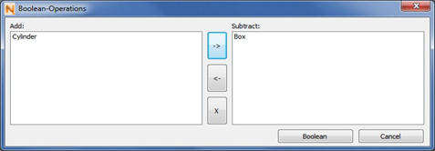
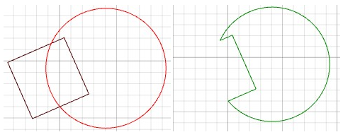
Top: Settings for a Boolean Operation. The box shall be subtracted from the cylinder. Bottom left: The two overlapping slices before the operation. Bottom right: The resulting slice.
Create Offsets of Slices
With the Slice Commander, you can create two-dimensional offsets of slices. They can be used, for example, to compensate for expected inaccuracies during production with a machine.
 With the option Create Offset in the context and Extras menu, you can create either an inner or an outer offset of the slice. It creates a new slice, of which the layers are based on the shape of the original layers, only that they are placed either within or without the original. In a dialog box, you can enter the preferred distance to the original contours, you can edit the roundness for curves of the offset, where it goes around corners of the original, and you can choose between an inner and an outer offset.
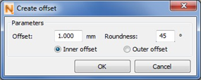
The dialog box for creating offsets.
This roundness is only relevant when it is necessary that the offset forms a curve, which is the case with outer corners for outer offsets and with corners with a reflex angle for inner offsets (corners projecting inside). If the offset line lies on the inside of the corner of the original, a new corner is created with an identical angle.
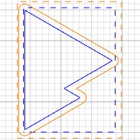
Inner and outer offset of original, blue slice.
The roundness angle represents the maximum angle of two adjacent points of the offset, with the original corner point as apex of the angle. Consequently, the offset curve becomes rounder and more precise, if the maximum angle is reduced.
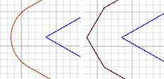
Roundness 1◦ (left) and 90◦ (right)
When you click on OK, a raw offset is created. This consists only of hatches parallel to the original hatches. Netfabb also displays lines connecting the end points of the offset hatches with the corner points of the original contour. If there goes around the outside of corners, the additional hatches connecting the open ends (according to your roundness settings) are also added to the offset.
If Preview Calculations is ticked, a preview of the finished offset is displayed instead of the raw offset. This offset is finished, if you apply the calculation in the context menu. Calculations are applied automatically when you export the slice. So, you can wait with applying these calculations, which can take some time and disrupt your workflow with complicated slice data, until you export.
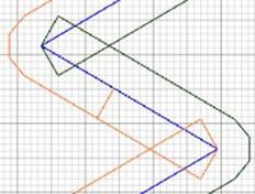
Raw offsets