To print a part, the supported area must be filled with a support type. There are three different support types:

Three different support types: Bar Support (F4), Polyline Support (F5) and Volume Support (F6).
Bar Support

 To create a bar, simply choose the according icon and double click on the surface you want to support. A vertical bar will be projected downwards. It’s also possible to set a new anchor and project it up/down in order to create a bar afterwards. To create a Bar Support, at least two anchor-points are needed.
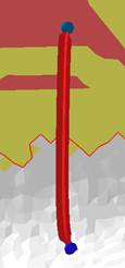
Example of a simple bar support with a cross-shaped cross section.
You can also not only make a simple bar, but a bouquet-structure. Therefore, create a bar, add another anchor on the bar and use this one for creating another bar.
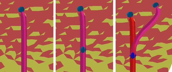
Left: create a bar. Middle: create another anchor on the bar with the create anchor icon. Right: Go back to the create new bar function and use the new anchor to connect it with another spot on the part.
Bars can have many different shapes. Here are a few examples:

Left: Straight bar with a solid contour. Middle: Crooked bar with a right angle on the part and a cross contour. Right: crooked, solid bar with bouquet-structure.
Contours, part-bar-distances and breaking points can be adjusted in the Edit tab, or if you right-click on the bar and go to Edit entity. Find a list of all parameters and their meaning below.
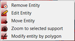
The context menu of a bar, in order to remove or edit an entity.

In the Edit tab, you can define the parameters for each bar.
By clicking on the blue gearwheel you can also save your custom settings to one of the three sets. Furthermore you can also load them, or import/export them to and from your computer.
| Support properties | meaning |
| Bar contour | Describes the shape of a bar. The contour can occur as a cross, which is an open hatch and not a volume. Should your printer not be able to process open hatches you can also set it to solid cross, or solid bar. |
| Angle at top | Defines the shape of the upper part of the cross-contour. The contour can e.g. either look like a pillar (0°) or an arrowhead (45°). |
| Distance to part | Describes the distance between part and support. If there is a negative value, the support will be extend into the part. |
| Width on part | Defines the contour-width on the top of the bar. |
| Width on platform | Defines the contour-width on the bottom of the bar. |
| Breaking point | A kink (breaking point) will appear at the upper end of the bar. It is much easier to detach the support from the part with breaking points. |
| Breaking point | Toggle yes or no to activate the breaking point. |
| Breaking point width | Defines the strength of the bar on the breaking point. It will be easier to remove the bar with a thinner breaking point. |
| Width on end | It is possible to make the part wider at the end of the breaking point. This can increase the adhesion of the bar on the part. |
| Breaking point height | Describes the height between the anchor-point on the part and the kink on the breaking point. The bigger the value, the longer the distance. |
| Height on start | Sets the height on the start of the breaking point. |
| Height on end | Sets the height on the end of the breaking point. |
| Right angle on part | Indicates whether the bar runs perpendicularly to the part (this usually results in a curved bar), or straight between start and end anchor. |
| Distance to right angle | Defines the length of that part of the bar that runs to the part perpendicularly. (The strength of the curve will be affected.) |
| Smoothing distance | Defines, how many steps must be made to smoothen a bar. The smaller the distance, the stronger the smoothing and the more triangles will be used. |
| Pad on platform | |
| Pad on platform | Toggles whether the Pad is active or not. |
| Pad width | Sets width of the created cross on the platform. |
| Pad height | Sets the height, the Pad is going to have on the bar. |
Polyline Support
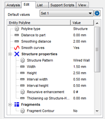
To create a Polyline Support, at least two anchor-points are needed. Line types, structure properties, fragments and connection types can be adjusted in the Edit tab, or if you right-click on the bar and go to Edit entity. Find a list of all parameters and their meaning below.
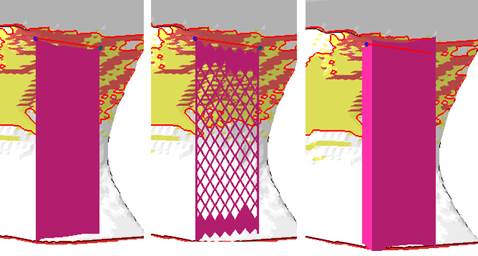
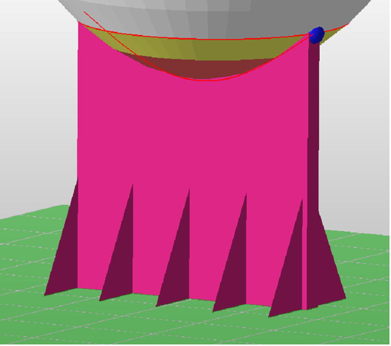
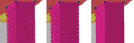
Examples of polyline support: Left: Polyline with a thin line. Middle: Polyline support as a structure. Right: Polyline as a massive wall.
| Support properties | meaning |
| Polyline type | Defines if the structure will be filled with a thin line, as massive wall or with a special structure. |
| Distance to part | Sets the distance between part and support. If there is a negative value, the support will be extend into the part. |
| Smoothing distance | Defines how many steps will be used to smoothen a polyline. The smaller the distance, the stronger the smoothing and the more triangles will be used. |
| Smooth curves | Defines, if the polyline should be smoothed, or if there should remain sharp edges on the anchor points. |
| Structure properties | |
| Structure pattern | Defines the type of the support structure. The pattern can be consist of a wired wall, a punched plate or a solid wall. |
| Width and Height | Set Width and Height of the Polyline |
| Interval width and height | Describe the distance between two structure units. |
| Thickening up structure-hatches | You can thicken open shell hatch structures like the wired wall for example. Just set the needed thickness in millimeters. |
| Fragments | The support will be divided in several fragments (will look like a grid). Due to the separation, it’s easier to remove the support from the part. |
| Fragment contour | Using the dropdown menu, the fragmentation can be turned on or off. |
| Connection | This defines the connection between support, part and platform ground. |
| Part connection | This group defines the connection between part and support. |
| Top/Bottom | Top part connection sets the values for the connection between the part and the support structures. Bottom part connection sets the values for the connection between the connection layer and the actual support structure |
| Connection | Describes the type of the connection. The type can consist of strips, trapezes, breaking points or triangles. |
| Connection width | Sets the width of the connections. |
| Pin distance | Sets the distance between the pins for one structure |
| Connection height | Sets the height of the connections. |
| Pins per structure | With trapezes, breaking points and triangles you can set the number of pins per structure unit. |
| Platform connection | This group defines the connection between part and platform ground. |
| Connection | Describes the type of the connection. The type can be a strip, trapeze, breaking point or triangle. |
| Connection width | Sets the width of the connections |
| Connection height | Sets the height of the connections. |
| Hatches | Defines the number of hatches. Hatches are stripes at the bottom of a support structure. The more Hatches exists, the wider the area, on which the support structure is located. |
| Hatch distance | Describes the distance between two hatches. The density of the structure will be affected. |
| Pins per structure | Sets the number of pins at the bottom of the structure. Can be used to change the connection to the platform. On each step the number of pins will be doubled. |
| Triangles on platform | Defines, if the bottom of the polyline support should be strengthened with triangles that are rotated by 90°.
 |
Volume Support
To create a Volume Support, at least three anchor-points are needed. Line types, structure properties, fragments and connection types can be adjusted in the Edit tab, or if you right-click on the bar and go to Edit entity. Find a list of all parameters and their meaning below.
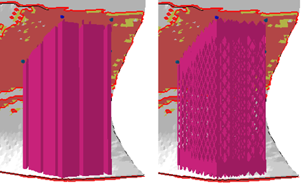
Left: a massive volume support divided in fragments. Right: a volume support that includes a structure.
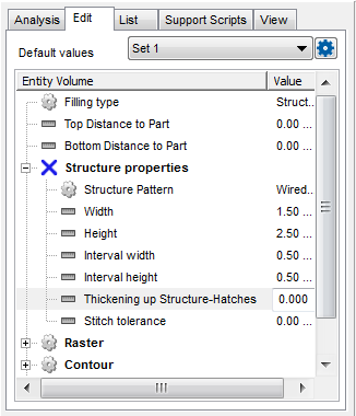
Edit the support properties of the volume support.
| Support properties | meaning |
| Type | Defines if the volume will massive or filled with a structure. |
| Top distance to part | Describes the distance between part and support. |
| Bottom distance to part | Describes the distance between part and platform. |
| Structure properties | |
| Structure pattern | Defines the type of the support structure. The pattern can consist of a wired wall (left), a punched plate (middle) or solid (right).
|
| Width and height | Define the width and height of a structure unit: the width and height from a hole of the punched plate or a wire of the wired wall. |
| Interval width and height | describes the distance between two structure units |
| Thickening up Structure-Hatches | You can thicken open shell hatch structures like the wired wall for example. Just set the needed thickness in millimeters. |
| Stitch tolerance | Set a tolerance in mm up to which a gap between the structures is not going to be stitched |
| Raster | |
| Rotate by Z | Sets the angle between inner- and outer support structure. Changing the value, the inner structure will rotate by this angle. |
| Hatch distance | Defines the distance between the inner structure units. The number of inner structure units and the density will be affected. |
| Filling strategy | Defines in which directs the outer contour of the volume support is going to be filled: In X and Y directions, Just in Y, or no filling at all. The option just in X can be created by using just in y and rotating the support by 90°. |
| Contour | Settings for the outer contour of the support structure. |
| Smooth contour | Defines, if the contour should be smoothed, or if there should arise sharp edges on the anchor points. |
| Contour around support | The contours of the volume structure can be encased or stay free. |
| Smoothing distance | Defines, how many steps will be used to smooth the structure. The smaller the distance, the stronger the smoothing and the more triangles will be used. |
| Connection | This group defines the connection between support, part and platform ground. |
| Part connection | This group defines the connection between part and support. |
| Top/Bottom | Top part connection sets the values for the connection between the part and the support structures. Bottom part connection sets the values for the connection between the connection layer and the actual support structure. |
| Connection | Describes the type of the connection. The type can be a strip, triangle, trapeze or breaking point. |
| Connection width | Sets the width of the connections. |
| Pin distance | Sets the distance between the pins in one structure |
| Connection height | Sets the height of the connections. |
| Pins per structure | Sets the number of pins at the bottom of the structure. Can be used to change the connection to the platform. On each step the number of pins will be doubled. |
| Platform connection | This group defines the connection between support and platform ground. |
| Connection | Describes the type of the connection. The type can be a strip, triangle, trapeze or breaking point. |
| Connection height | Sets the width and height of the connections. |
| Hatches | Defines the number of hatches. Hatches are stripes at the bottom of a support structure. The more Hatches exists, the wider the area, on which the support structure is located. |
| Hatch distance | Describes the distance between two hatches. The density of the structure will be affected. |
| Connection by layer | It is also possible, to connect the structured support to the part by a layer. A layer can cause a higher surface quality of the part, because it is an exact copy of the supported (red and yellow marked) area. |
| Create layer | Toggles whether a layer is created or not. |
| Refine layer | If it is not possible to create a copy of the layer surface, the supported structure will be created with a triangulation of anchor points. The accuracy of the triangulation can be affected by the refinement. |
| Top layer height | Defines the thickness of the layer. |
| Top layer distance to structure | Sets the distance between the top layer and the structure. |
| Pin type | Describes the type of connection between part and layer. The connection can consist of a cross or cube structure, or without pins. |
| Pin width | Sets the width of a pin. |
| Pin density | Defines the density of the pin structure. The smaller the value, the smaller the smaller the distance between two pins. |
| Fragments | The support will be separated in several parts. (fragments) Due to the separation, it is easier to remove the support from the part. |
| Raster | |
| Fragments | Turn fragments on or off |
| Fragment size X | Fragment size in X direction. |
| Fragment size Y | Fragment size in Y direction. |
| Fragment gap | Describes the distance between two fragments. |
| X shrinkage | Shrinks the fragment on the bottom end of the x axis, to have a wider fragment at top, whose size decreases to the set value |
| Y shrinkage | Shrinks the fragment on the bottom end of the y axis, to have a wider fragment at top, whose size decreases to the set value |
| Contour | |
| Fragment contour | Toggle fragment contour on and off |
| Fragment contour length | Defines the length of a fragment unit. |
| Fragment contour gap | Defines the gap between two fragment units |
List of all support entities
An overview of all entities can be found in the tab List. Manual added supports are listed there as well as the automatically created ones. Each entity is sorted in a cluster.

Left: In the List tab you find an overview of all clusters and entities. Right: A selected support cluster.
If there is a structure (cluster) or a single bar selected and the checkbox Zoom to selection is active, a zoom to the selected support is executed and the Bottom view is selected. The checkbox Set clip plane for selection is helpful when you need to view support which does not reach the platform plane. When checked, the Z clipping plane and hiding functionality will be adjusted automatically to allow for a more efficient workflow. Hide non-selection displays no other support entity than the selected one.