Cluster Detection
The (red and yellow marked) supported area of a part is called Cluster. For each area-based automatic support action it is possible to define a cluster, on which the area support will be applied.
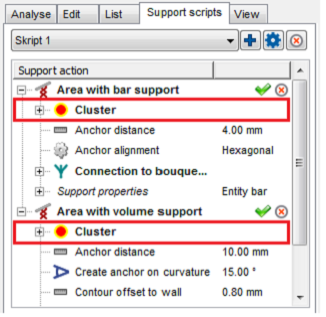
Script with several support actions.
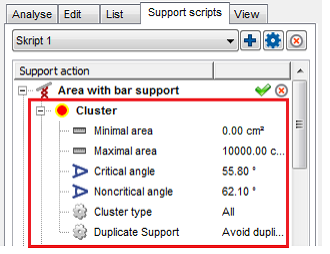
Tree view of a cluster action.
| Cluster | |
|---|---|
| Minimal area | Defines the size an area at least may have to be supported. |
| Maximal area | Defines the size an area at most may have to be supported. |
| Critical angle | The larger the critical angle, the larger the red highlighted area. This must be supported. The angle values depend mostly on your machine and material. |
| Noncritical angle | The larger the noncritical angle, the lager the yellow highlighted border-area. This area is used for building clusters together with the red area. This avoids having a lot of small supported spots, instead of making one larger supported area. |
| Cluster type | |
| Duplicate support | The sharper the angle of the support area, the less support is needed there. The duplication defines, if areas which need more support (flat angle) should get the support twice. Or if there should not appear a overlapping structure. |
Edge with Polyline Support
| Minimal edge length | Defines the length an edge at least must have to be supported. |
| Maximal edge length | Defines the length an edge at most may have to be supported. |
| Maximal polyline curvature | Sets the curvature of a polyline may have at most. If this maximum value will be passed, a new polyline begins. |
| Maximal edge angle to XY-plane | Describes the maximum angle between an edge and the XY-plane. If the maximum angle will be passed, the edge is not detected. |
| Create anchor on curvature | Defines on which curvature of the edge a new anchor point will be added. The anchor points will be created around the edge. |
| Anchor distance | Sets the distance between two anchor points. |
| Contour offset | Sets the distance between an anchor point and a clear area. |
| Startpoint distance | Sets the border distance between the edge and the start of the support structure |
| Support properties | Are described in the Polyline Support section. |
Area with Volume Support
| Cluster | Refer to the Cluster Detection section above. |
| Contour accuracy | Describes how precise the contour is |
| Contour offset to wall | The anchor points along the contour can be moved further apart from the edge. The offset describes the distance from the edge to the next wall. |
| Free contour offset | Describes the distance between an anchor point and the next edge. |
| Support properties | Are described in the Volume Support section. |
Area with Bar Support
| Cluster | Refer to the Cluster Detection section above. |
| Anchor distance | Defines the space between two anchor points or bars. |
| Anchor alignment | There are two ways to support the critical area with bar: Rectangular means, that the support structure is arranged rectangular to the area. Hexagonal means, that the structure is arranged hexagonal, which enables to arrange more bars on the same area. |
| Offset to border | Defines a distance at the border of the cluster, where no bars are being placed |
| Connection to bouquet-structure | Not every bar has its start point at the bottom of a platform. It is possible to create a branch of the bouquet-structure, which saves time to construction and substance too. |
| Diameter of bouquet-structure | Defines the maximum diameter of the whole bouquet-structure. |
| Height of bouquet-structure | Describes the height between the first branch of the bouquet-structure and the part. |
| Recursive depth of bouquet-structure | Sets the limit of branches per bar between the first branch and the part. |
| Support properties | Are described in the Bar Support section. |
Area with Polyline Support
| Cluster | Refer to the Cluster Detection section above. |
| Anchor distance | The detected area will supported with polylines. The anchor distance defines the space between two anchor points for each polyline. |
| Hatch distance | Sets the distance between two polylines. |
| Rotate by Z | Rotates the arrangement of the polylines by the entered value. |
| Wave amplitude | Defines the distance between every intermediate anchor point from a polyline. A value >0 creates a wave (if polyline is smoothed) or a zig zag pattern. (if polyline is not smoothed) |
| Support properties | Are described in the Polyline Support section. |
Down-oriented Point Bar Support
| Maximal area | Defines the size of the area that may be supported. |
| Critical angle | The larger the angle, the larger the red highlighted, supported main area. This must be supported. The angle values depend mostly on your machine and material. |
| Noncritical angle | The larger the angle, the lager the yellow highlighted border area. This area is used for building clusters together with the red area. |
| Anchor distance | Sets the distance between two anchor points or bars. In this way a support between two bars close to each other can be avoid. |
| Support properties | Are described in the Bar Support section. |
Surround Volume by Polyline
| Minimal Edge Length | Defines the length an edge at least must have to be supported. |
| Maximal Edge Length | Defines the length an edge at most may have to be supported. |
| Border Type | Toggles between all, free border or border to wall. The settings help to prevent the polyline from melting with any part wall, if it’s set to free boarder. Boarder to wall will only place polylines when there is a wall next to the edge. |
| Contour Type | The action can also be performed on inner contours where it is not the outer edge of the cluster |
| Support Properties | Are described in the Polyline Support section. |
Skeleton with Polyline Support
| Cluster | Refer to the Cluster Detection section above. |
| Minimal Edge Length | Defines the distance between the contour and the volume supports, that is needed for a polyline to be created. |
| Anchor Distance | Anchor distance defines how much space should be in between 2 polyline entities. The lower the distance the more polylines are going to be created. |
| Offset to Border | Defines a distance at the border of the cluster, where no bars are being placed |
| Support Properties | Are described in the Polyline Support section. |
Move entity
![]() You can also move and scale the entire support structure after the script has been calculated. To do so, right-click the part and choose
Move Entity, or use the dropdown menu in the icon bar. A dialog will open and provide several options.
You can also move and scale the entire support structure after the script has been calculated. To do so, right-click the part and choose
Move Entity, or use the dropdown menu in the icon bar. A dialog will open and provide several options.
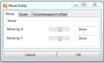
Move supports, scale them or even create an offset for volume support
For volume supports you can create an offset to the edge of the cluster

Supports as created by the script.
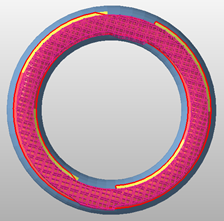
An offset of about 2mm was created to the edge of the cluster