 If you right-click on a slice in the screen or in the project tree and choose Export, you can save the slice as SLI, CLI, SLC, SSL, ABF, SLM, CLS, USF, CLF, PNG, BMP, SVG, DXF or PS file. It is the last step before manufacturing the part. The saved files can be read by 3D-printers and are built directly. If more than one slice is selected, all selected slices are exported as one file.
You can choose a file type in the submenu of the Export option in the context menu. After you click on a file type, a dialog box is opened where you can edit all export parameters. You can also change the file type again in that box.

The dialog box for exporting slices
At the top of the window, you can set the start height, end height and layer size. The layer count resulting from these settings is also specified.
The start height and end height determine the exported section of the slice. So, you do not have to export the whole slice, as you can leave out defined top and bottom sections. If you choose a start height in the middle of the part, for example, only the upper half will be exported.
The needed layer size usually depends on the machine you use for producing the part. When you start the export dialog, the layer size of the file is automatically that of your slice. If you know the necessary layer size when slicing the part, you should use that size at this stage already.
If you insert a layer size different to the layer size of the slice, Netfabb always takes the last slice in the Slice Commander. So, if you have a slice with the layer size 0.1 and export it with layer size 0.14, the first layer (0.14) will be the same as the original layer at 0.1, the second (0.28) will be the same as the original at 0.2, and the third (0.42) will be the same as the original at 0.4. The original layer at 0.3 will be left out. If you define a layer size below that of the original, some layers will be doubled. Below, there are the specific export settings. At the top of this box is a dropdown menu where you can choose the file type for the export. When the dropdown menu is closed, but still selected, you can also use the scroll button of your mouse to change the file type. The file type you need depends on the machine you use.

The format of the target file can be chosen in this dropdown menu.
After the file type, fill in a file name in the provided text field and choose a target directory in a file browser after you click on the "..." button. The specific export settings necessary depend on the chosen file type:
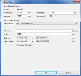
For SLI (Slice Layer Interface) and CLI (Common Layer Interface), the specific settings are the same. The units are length units for the calculation of slice contours, proportional to mm. They determine the resolution with which the slice layers are saved. With a lower value, the layers will be more precise, but the calculation may take longer. You can choose the calculation unit in a dropdown menu or enter a unit manually. The resolution determines the maximum size of the exported slice. With a bigger unit (and thereby lower resolution), you can export SLI files with a bigger outbox.

The specific settings for exporting a slice to an SLI-file.

Choose the length unit for the calculation of the slice.
Below that, the coordinates dimensions of the outbox are specified. You can read both the position and the size of the part in the X-Y-plane. In the first field are the lowest X- and Y-values. In the second field are the highest X- and Y-values.
The maximum outbox is the restriction by the file type. It depends on the length units you have chosen. The slice has to be within the boundaries specified here.
If the outbox of your slice is not completely within this area, the resolution is too high / the unit too low, and the file cannot be written in the SLI or CLI format. In that case, you will get a warning. With the button Fix Problem, the unit is set to the lowest functioning standard value. However, it could also be enough to reposition the slice, for example to move it to the origin.

If the slice file is too big to be written with the current resolution, you get this warning.
If the box Move Parts to Origin is ticked, the position of the exported parts is automatically adjusted so that they start at the coordinates X=0 and Y=0. If it is not ticked and the slices have negative X- or Y-coordinates, you get a warning. The SLI and CLI file formats do not support slices with negative coordinates. You can solve that problem by ticking Move Parts to Origin or clicking on Fix Problem (in which case Move Parts to Origin is ticked automatically). If you do not want the slice at the coordinates X=0, Y=0, you have to cancel the export dialog, move the slice to positive coordinates and start the export again.
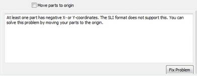
If a slice has negative X or Y-coordinates, you get a warning and you can move it automatically to X=0, Y=0 by clicking on Fix Problem.
For SLC files, you have dropdown menus to choose between the units mm or inch and to choose either Part, Support or Web as SLC type.

The specific settings for exporting SLC files.
For SSL (Stratasys Layer File) files, you have to choose which version of SSL files you want to export: SSL V0 or SSL V20. If you have chosen SSL V20, you can tick and untick the box Force open contours. If this option is activated, all contours are interpreted as open contours and no filling is inserted during the print.

The specific settings for exporting SSL files.
If you export ABF (Arcam Build Files) files, you have the options to calculate the slices in memory and to use compression to create smaller files. Calculating slices in memory needs very much main memory and is not recommended with very large files.

The specific settings for exporting ABF files.
For CLS (Concept Laser Slice Files), CLF (Common Layer File) and USF (Universal Slice Files), you can only change the file name and 1target directory and you cannot edit any other specific settings.
The SLM format (Selective Laser Melting) requires specifications for the build style, laser focus, laser power and laser speed. To change those, open the SLM Export Settings with a double click on any value in the table. Additionally, you can determine the point distance and point exposure time. The output will be one .slm file.
Convert to Model
When exporting into a model, the slice data are converted back into a triangle mesh. When you choose convert to model in the context menu, an own dialog box is opened, in which you can edit accuracy and refinement, and you can choose to smooth the result. The accuracy determines the preciseness of the calculation. For the export, which raster cells in a three-dimensional raster are occupied by a slice layer. Those cells will be part of the STL. With this procedure, you get an effect of steps in the part as big as the accuracy/raster size and the file might need very much triangles. Thus, even small and simple parts may have a huge data volume. Refinement and smoothing are measurements against this steps-effect. To make sure that bottom and top are closed, check the respecting box.
Export Image Files
If you export a slice as image files or vector graphics, Netfabb creates an image of each slice layer, either as SVG, DXF, PNG, BMP or PS file. Each layer is exported into a separate image file.
In the specific export settings for SVG (Scalable Vector Graphics), BMP (Windows Bitmap) and PNG (Portable Network Graphics) files, you can choose between two registers, one for the export target and one for export parameters.
For the Export Target, you first have to choose in a dropdown menu, if you want to copy the image file in a directory or if you want to save them in a TAR or ZIP archive file. Then, fill in a file name, which will be supplemented by the layer number of each image file, and choose a target directory.
When exporting SVG files, these are the only options for the export target, but for PNG and BMP files, there are several other options:
The dialog box for exporting slices as models.
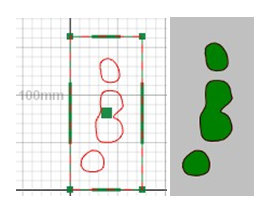
Left: A slice file on the screen. Right: The depiction of the same slice layer in a PNG-file.
Below the field for entering your file name, you can change the resolution and the size (in pixels) of the slice images. Those two settings depend on each other, and if you change one, the other is adjusted automatically.
If the box Enable anti-aliasing is ticked, you will have reduced aliasing and raster effects in your image files.
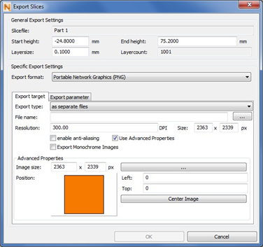
The settings for the export target for image files.
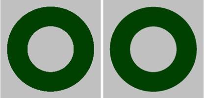
Left: An exported slice as png without aliasing effects. Right: The equivalent image with enabled anti-aliasing.
If you tick the box Use Advanced Properties, additional options become available: You can change the size of the whole image either by inserting a pixel size manually or by choosing a standard size after clicking on the "..." button. This does not have any influence on how big the slice is depicted. However, if you change the size of the slice depiction above, the height of the entire image is adjusted to the new height and the width is scaled proportionally.

In the colored field, you can adjust the position of the slice in the image.
After setting the image size, you can change the position of the slice depiction on the image. In the Position field, the background is drawn blue and the slice is illustrated in orange. You can simply move the slice around by drag & drop.
To the right, you can see the distance between the slice depiction and the frame of the image. The fields Left and Top specify the number of pixels from the left and top side of the whole image to the slice depiction. If you enter new values here, the position of the slice is adjusted accordingly. If you click on Center Image, the slice is moved back into the center of the image. If you create an image which is smaller than the slice depiction or if you just move the slice across the edge of the image, it is possible to export only a section of the slice into your image files.
In the export parameters, you can choose how your slice shall be depicted and which colors the images will have. You can tick boxes whether you want to include closed contours, the filling of closed contours, and lines along open contours and hatches. For the lines, you can enter the thickness with which they are drawn in the image. Furthermore, after clicking on the "..." button on to the right, you can edit the color of all elements of the image as well as the background color. When you export SVG files, the filling and the background are always white and cannot be changed.
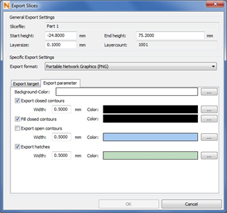
The settings for the export parameters for image files.
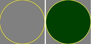
Left: A slice image with grey background, where only the closed contour is visualized. Right: Here, the contour is filled and a different color is assigned.
For DXF (Drawing Interchange Format) files you can only choose to export either separate files, a TAR archive or a ZIP archive in the dropdown menu and select a target folder.

The specific settings for exporting DXF files.
For PS (Adobe Postscript) files, all images are saved in one file, with one page per layer. You can choose, if the inside or the outside of the slice is black (with the box Inverted) and you can choose either the portrait or the landscape page format as orientation.
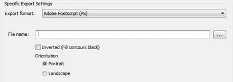
The specific settings for exporting PS files.