Set anchors


 The support is not connected directly with the part. It's connected from the floor up to an anchor-point, which is located on the part. If a support-mode is selected, anchor-points can be moved, created, or deleted.
In the context menu of an anchor, you can either project it vertically up or down (it will be placed on the platform or on the part), project it directly on the platform or remove all unused anchors.
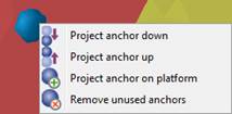
The anchor context menu for projecting or removing an anchors.
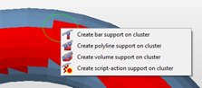
Use the symbols in the toolbar to manually add support structures to the surface.
Manually add support structures
 Create new bar will enable you to create support bars vertically by double clicking anywhere on the surface. With a single click an anchor is created. Two anchors will be connected by a horizontal bar.
 Create new polyline creates a lateral line of support structures alongside the part’s surface. By single clicking on the surfaces in need of support anchors are created which will be connected by a single polyline.
 Create new volume support lets you set anchors by a single click on the surface of the part, as well. At least three anchors have to be placed in order to create a support structure. To generate a voluminous structure it is recommended to arrange the anchors in rectangular shape.
Mark Cluster manual
 It is also possible to manually create clusters with no relation to the downskin analysis. Activate the mark cluster manual symbol and use it to paint all surfaces that are in need of support. In the view tab the cluster diameter can be set to fit the parts size. This will create a new cluster, to place the different support types on semi automatically, or by using support actions from previously defined support scripts. Full support scripts cannot be run on manually created clusters, as they define their own clusters. Single support actions that have been defined for support scripts, however, can be applied here.
Semiautomatic supports for manually created clusters
To avoid sharp corners and edges on the clusters, some areas are flagged as non-critical areas (in yellow). Supports are not being created here but they can only translate from a red area into a yellow one. Which clusters are being flagged red and yellow depends on the center of gravity of each triangle and whether it is inside or outside of the circular selection tool. Centers inside of the circle are critical (red) while centers outside of it are non-critical (yellow). So if you want to turn a yellow cluster into a red one simply click right onto the center of the respective triangle.
To support edges
You can add Polyline support to individual edges highlighted in the main view. Right-click the highlighted edge of choice and use the option offered.
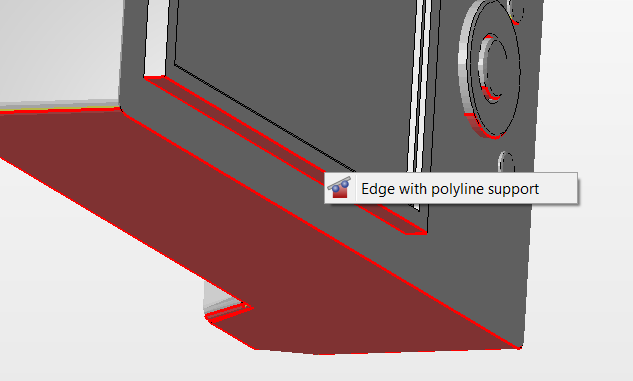
Right-click any of the highlighted down edges and add the support through its context menu
To draw Polyline support
While in 2D Mode of Cluster, you can draw a polygon line and have Netfabb create support along this line.
Launch Enhanced Support Module, then pick 2D mode of Cluster from the cluster's context menu.
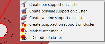
2D mode of cluster is the last item in a cluster's context menu while Enhanced Support Module is active.
Use Create new Polyline and draw support as needed. Use the Reset button in case you need to revert. Then, use Extend Support Area to finally create the support structure. Note that in this feature, you cannot close the Polyline.

Buttons from left to right: Modify entity by polygon, Create new polyline, Extend support area, Remove support area, Reset, Cancel.