Slide Line Contact Parameters
Description: Defines the parameters for a slide line contact region.
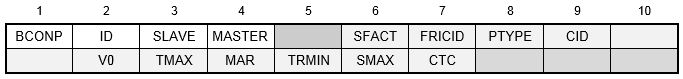
Format:
Example:

| Field | Definition | Type | Default | ||||||||
|---|---|---|---|---|---|---|---|---|---|---|---|
| ID | Contact region identification number. | Integer > 0 | Required | ||||||||
| SLAVE | Slave region identification number. | Integer > 0 | Required | ||||||||
| MASTER | Master region identification number. | Integer > 0 | Required | ||||||||
| SFACT | Stiffness scaling factor used to scale the penalty values determined automatically. See Remark 4. | Real > 0.0 | 1.0 | ||||||||
| FRICID | Contact friction identification number. See Remark 5. | Integer ≥ 0 or blank | |||||||||
| PTYPE | Penetration type. See Remarks 6 and 7.
|
1 ≤ Integer ≤ 8 | 1 | ||||||||
| CID | Coordinate system identification number to define plane of contact. See Remark 9. | Integer ≥ 0 or blank | 0 | ||||||||
| V0 | Penetration edge offset. See Remark 10. | Real | 0.0 | ||||||||
| TMAX | Maximum allowable penetration used in the adjustment of penalty values normal to the slide line. A positive value activates the penalty value adjustment. See Remark 11. | Real ≥ 0.0 | See Remark 11 | ||||||||
| MAR | Maximum allowable adjustment ratio for adaptive penalty values K and FSTIF. See Remark 12. | Real > 1.0 | 100.0 | ||||||||
| TRMIN | Fraction of TMAX defining the lower bound for the allowable penetration. See Remark 13. | 0.0 ≤ Real ≤ 1.0 | 0.001 | ||||||||
| SMAX | Maximum allowable slip used in the adjustment of penalty values parallel to the contact plane (FSTIF). A positive value activates the penalty value adjustment. See Remark 14. | Real ≥ 0.0 | 0.0 | ||||||||
| CTC | Contact thermal conductance. See Remark 15. | Real ≥ 0.0 | ∞ |
Remarks:
- Contact region identification number must be unique with respect to all other BCONP identification numbers.
- The SLAVE field defines the slave line by referencing a BLSEG Bulk Data entry. The width of each slave segment is defined via the BWIDTH Bulk Data entry. The width must be defined to get the proper contact stress if symmetrical penetration is specified.
- The MASTER field defines the master line by referencing a BLSEG Bulk Data entry. The width of each master segment is defined via the BWIDTH Bulk Data entry. The width must be defined to get the proper contact stress.
- SFACT may be used to scale the penalty values that are determined automatically based on adjacent diagonal stiffness matrix coefficients. Additionally, penalty values calculated may be further scaled by the SLINEKSFACT model parameter (see Section 5,
Parameters, for more information on
SLINEKSFACT). The penalty value is then equal to
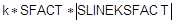 , where k is a value selected for each slave node based on the diagonal stiffness matrix coefficient and SFACT is specified in the SFACT field above. Note that the SLINEKSFACT value applies to all contact regions in the model. Penalty values are normally recalculated every time there is a change in stiffness. However, if SLINEKSFACT is negative, penalty values are not recalculated. This setting is recommended if problems with convergence are encountered.
- The referenced FRICIC is the identification number of the BFRIC Bulk Data entry. The BFRIC defines friction properties for the contact region.
- For unsymmetric contact, only the penetration of the slave node into the master segments is checked. This may lead to the master nodes penetrating the slave segments. This error is reduced as the mesh density is increased. For symmetric penetration, both the slave and master nodes are checked for penetration. This is accomplished by generating a slave node, master segment element using the MASTER line for the slave nodes and the SLAVE line for the master segments.
- Welded contact behavior is accomplished by selecting the unsymmetric or symmetric welded contact setting (3 or 4). With either setting the element will behave the same in tension as in compression and will not slide. Note that for linear solutions general contact will default to welded behavior. Bi-directional sliding contact behavior is accomplished by selecting the unsymmetric or symmetric bi-directional contact setting (5 or 6). With either setting the element will act similar to a welded contact element in tension and compression, but will slide in-plane. Bi-directional sliding contact is available in all solutions. Rough contact behavior is accomplished by selecting the unsymmetric or symmetric rough contact setting (7 or 8). With either setting the element will act similar to a general contact element in tension and compression, but will not permit sliding in-plane.
- This element will default to welded contact in linear solutions including linear static analysis with linear contact enabled. A nonlinear solution must be selected for general contact behavior.
- Figure 1 shows a typical slide line contact definition. The slide line coordinate system z-axis defines the slide line contact plane. An alternate coordinate axis other than the z-axis may be specified using PARAM, SLINEPLANEZDIR (see Section 5, Parameters, for more information on SLINEPLANEZDIR). Relative motions outside the slide line plane are ignored and should be small compared to a typical master segment. The normal direction for a slide line segment is formed from the cross product of the slide line plane vector and the vector from master node 1 to master node 2. The definition of the coordinate system should be such that the normal direction points toward the slave region. For symmetric penetration the normals of the master and slave segments must face each other. This is generally accomplished by ordering the nodes on the master and slave lines either clockwise or counterclockwise depending on the direction of the slide line plane.
- A positive value of V0 offsets the contact line in the element y-direction and results in a contact condition occurring when a slave node penetrates the offset line.
- There are two methods for adaptive stiffness updates normal to the slide line: proximity stiffness based and displacement based.
- When TMAX ≠ 0.0, the displacement based stiffness update method is selected. The value specified defines the allowable penetration of the slave node into the master line. The recommended TMAX value is between 1% and 10% of the element thickness for plates or the equivalent thickness for other elements that are connected to the contact element.
- When TMAX = 0.0 (default), the update method selected is dependent on the SLINESLIDETYPE and SLINEMAXDISPTOL model parameter settings. When SLINESLIDETYPE is set to DYNAMIC, the proximity stiffness based update method is selected. When SLINESLIDETYPE is set to STATIC, the displacement based stiffness update method is selected where SLINEMAXDISPTOL defines the default TMAX value using

where
 is the total length of the master slide line. See Section 5,
Parameters, for more information on
SLINESLIDETYPE and
SLINEMAXDISPTOL.
is the total length of the master slide line. See Section 5,
Parameters, for more information on
SLINESLIDETYPE and
SLINEMAXDISPTOL.
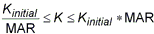
- The maximum adjustment ratio MAR defines the upper and lower bounds of the adjusted value by:
- TRMIN is used for the penalty value adjustment and defines the lower bound for the allowable penetration computed by TRMIN * TMAX. The penalty values are decreased if the penetration is below the lower bound.
- There are two methods for adaptive stiffness updates parallel to the contact plane: proximity stiffness based and displacement based. If SMAX ≠ 0.0, the displacement based update method is selected. When SMAX = 0.0 (default), the proximity stiffness based update method is selected. If FSTIF is specified, it will be used as the penalty stiffness for stick when the proximity stiffness method is used. If SMAX ≠ 0.0, the FSTIF value will be adjusted internally to achieve the SMAX displacement specified.
- The contact thermal conductance CTC is defined as:

where
 is the change in temperature between the slave node and average of the master nodes, and
q is the heat flux through the slide line. Contact thermal conductance is only applicable in heat transfer solutions.
is the change in temperature between the slave node and average of the master nodes, and
q is the heat flux through the slide line. Contact thermal conductance is only applicable in heat transfer solutions.
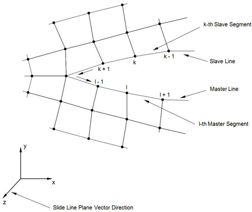
Figure 1. Slide Line Contact Definition