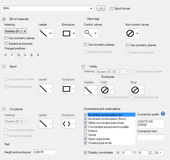
Sets the formatting for annotations on isometric drawings.

- Iso Style
-
Displays a list of available iso styles.
- Annotations Shown on Drawings
-
Specifies which tables have callout annotations.
Bill of Materials
- Indexing
-
Specifies whether numbering is alphabetic or numeric.
- Leader Line
-
Specifies whether a leader line connects the object to its annotation, with or without an arrow. You can also choose Do Not Display a leader line.
- Enclosure
-
Specifies the shape of the enclosure, circle, diamond, hexagon, rectangle, oval, square brackets, diamond brackets, or round brackets. You can also choose No Enclosure.
- Expand Enclosures
-
Expands graphics to accommodate annotation text. Some enclosure symbols always expand. Ignored when using Isometric planes.
- Use Isometric Planes
-
Displays annotations skewed in a standard isometric plane.
- Flanged Prefixes
-
Specifies a callout prefix for Flanges (F), Gaskets (G), or Bolts (B).
Valves
- Show tag number annotations for
-
Specifies the type of valves to be annotated, control and non-control valves
- Control valves
-
Specifies the annotation type for a control valve. You can also choose Do Not Display.
- Non-control valves
-
Specifies the annotation type for all other (non-control) valves.
Spools
- Numbering
-
Specifies how the annotations are numbered. The options are as follows:
- Automatic (numeric)
- Automatic (alphabetic)
- Automatic (LineNum-numeric)
- Automatic (LineNum-alphabetic)
- Use spool number from model
Welds
- Numbering
-
Specifies whether numbering is alphabetic or numeric. Or you can use a property from the model.
- Welds to Number
-
Specifies whether to number all welds, shop welds, or fields welds.
- Enclosure Type (Shop)
-
Specifies the enclosure types for a shop weld.
- Enclosure Type (Field)
-
Specifies the enclosure types for a field weld.
Cut Pieces
- Numbering
-
Specifies whether numbering is alphabetic or numeric.
Text
- Height and enclosure
-
Specifies iso text height for annotations. For enclosure graphics, symbols are scaled by this value.
Connections and Continuations
- List in box
-
Specifies which end connections coordinates are displayed for the selected iso type. Options are:
- Iso sheet continuation (to)
- Iso sheet continuation (from)
- Other connected pipe lines
- Connected equipment nozzles
- Vents
- Drains
- Open pipe ends
- Closed pipe ends
Note: Iso Sheet Connection (to) and Iso Sheet Connection (from) only work through a split. Non-split connections annotation should use Other connected pipe lines.
- Show End Connection Annotation on Iso
-
Specifies whether end-connection annotations appear on the isometric drawing.
- Connection text
-
Specifies the connection text. Enter property names in angled brackets.
- Append coordinates and elevation
-
Specifies whether coordinates and elevation information is to be added to the annotation.
- Coordinate Prefixes
-
Specifies prefixes for the X, Y, and Z coordinates.