Forms
Creating Forms
Similar to family creation, the conceptual design environment provides the ability to create new forms. The following types of forms can be created: extrusions, revolves, sweeps, swept blends, lofts, and surface forms. Rather than using the Blend, Extrusion, Revolution, Sweep, and SweptBlend classes used in Family creation, Mass families use the Form class for all types of forms.
An extrusion form is created from a closed curve loop that is planar. A revolve form is created from a profile and a line in the same plane as the profile which is the axis around which the shape is revolved to create a 3D form. A sweep form is created from a 2D profile that is swept along a planar path. A swept blend is created from multiple profiles, each one planar, that is swept along a single curve. A loft form is created from 2 or more profiles located on separate planes. A single surface form is created from a profile, similarly to an extrusion, but is given no height.
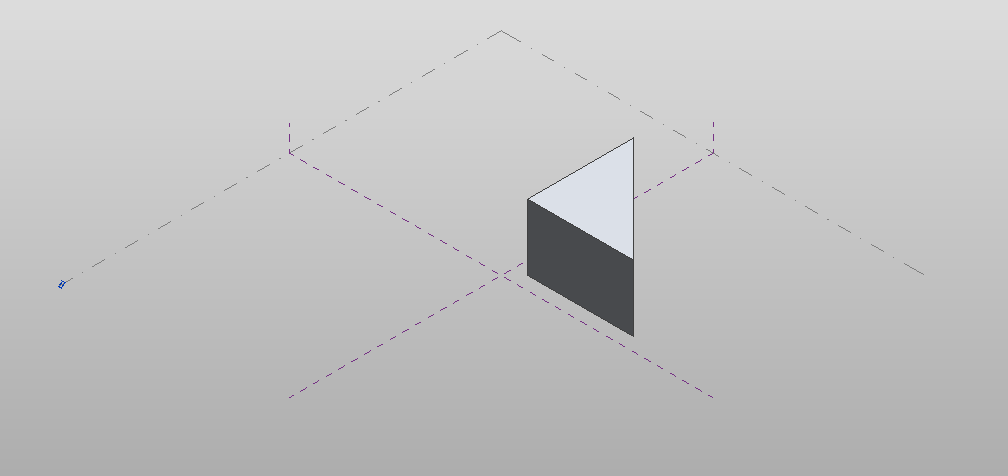
The following example creates a simple extruded form. Note that since the ModelCurves used to create the form are not converted to reference lines, they will be consumed by the resulting form.
|
Code Region 14-3: Creating an extrusion form |
private Form CreateExtrusionForm(Autodesk.Revit.DB.Document document)
{
    Form extrusionForm = null;

    // Create one profile
    ReferenceArray ref_ar = new ReferenceArray();

    XYZ ptA = new XYZ(10, 10, 0);
    XYZ ptB = new XYZ(90, 10, 0);
    ModelCurve modelcurve = MakeLine(document, ptA, ptB);
    ref_ar.Append(modelcurve.GeometryCurve.Reference);

    ptA = new XYZ(90, 10, 0);
    ptB = new XYZ(10, 90, 0);
    modelcurve = MakeLine(document, ptA, ptB);
    ref_ar.Append(modelcurve.GeometryCurve.Reference);

    ptA = new XYZ(10, 90, 0);
    ptB = new XYZ(10, 10, 0);
    modelcurve = MakeLine(document, ptA, ptB);
    ref_ar.Append(modelcurve.GeometryCurve.Reference);

    // The extrusion form direction
    XYZ direction = new XYZ(0, 0, 50);

    extrusionForm = document.FamilyCreate.NewExtrusionForm(true, ref_ar, direction);

    int profileCount = extrusionForm.ProfileCount;

    return extrusionForm;
}

public ModelCurve MakeLine(Document doc, XYZ ptA, XYZ ptB)
{
    Autodesk.Revit.ApplicationServices.Application app = doc.Application;
    // Create plane by the points
    Line line = Line.CreateBound(ptA, ptB);
    XYZ norm = ptA.CrossProduct(ptB);
    if (norm.IsZeroLength()) norm = XYZ.BasisZ;
    Plane plane = Plane.CreateByNormalAndOrigin(norm, ptB);
    SketchPlane skplane = SketchPlane.Create(doc, plane);
    // Create line here
    ModelCurve modelcurve = doc.FamilyCreate.NewModelCurve(line, skplane);
    return modelcurve;
}
|

Figure 56: Resulting extrusion form
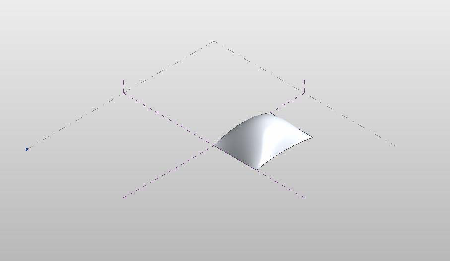
The following example shows how to create loft form using a series of CurveByPoints objects.
|
Code Region 14-4: Creating a loft form |
private Form CreateLoftForm(Autodesk.Revit.Document document)
{
        Form loftForm = null;

        ReferencePointArray rpa = new ReferencePointArray();
        ReferenceArrayArray ref_ar_ar = new ReferenceArrayArray();
        ReferenceArray ref_ar = new ReferenceArray();
        ReferencePoint rp = null;
        XYZ xyz = null;

        // make first profile curve for loft
        xyz = document.Application.Create.NewXYZ(0, 0, 0);
        rp = document.FamilyCreate.NewReferencePoint(xyz);
        rpa.Append(rp);

        xyz = document.Application.Create.NewXYZ(0, 50, 10);
        rp = document.FamilyCreate.NewReferencePoint(xyz);
        rpa.Append(rp);

        xyz = document.Application.Create.NewXYZ(0, 100, 0);
        rp = document.FamilyCreate.NewReferencePoint(xyz);
        rpa.Append(rp);

        CurveByPoints cbp = document.FamilyCreate.NewCurveByPoints(rpa);
        ref_ar.Append(cbp.GeometryCurve.Reference);
        ref_ar_ar.Append(ref_ar);
        rpa.Clear();
        ref_ar = new ReferenceArray();

        // make second profile curve for loft
        xyz = document.Application.Create.NewXYZ(50, 0, 0);
        rp = document.FamilyCreate.NewReferencePoint(xyz);
        rpa.Append(rp);

        xyz = document.Application.Create.NewXYZ(50, 50, 30);
        rp = document.FamilyCreate.NewReferencePoint(xyz);
        rpa.Append(rp);

        xyz = document.Application.Create.NewXYZ(50, 100, 0);
        rp = document.FamilyCreate.NewReferencePoint(xyz);
        rpa.Append(rp);

        cbp = document.FamilyCreate.NewCurveByPoints(rpa);
        ref_ar.Append(cbp.GeometryCurve.Reference);
        ref_ar_ar.Append(ref_ar);
        rpa.Clear();
        ref_ar = new ReferenceArray();

        // make third profile curve for loft
        xyz = document.Application.Create.NewXYZ(75, 0, 0);
        rp = document.FamilyCreate.NewReferencePoint(xyz);
        rpa.Append(rp);

        xyz = document.Application.Create.NewXYZ(75, 50, 5);
        rp = document.FamilyCreate.NewReferencePoint(xyz);
        rpa.Append(rp);

        xyz = document.Application.Create.NewXYZ(75, 100, 0);
        rp = document.FamilyCreate.NewReferencePoint(xyz);
        rpa.Append(rp);

        cbp = document.FamilyCreate.NewCurveByPoints(rpa);
        ref_ar.Append(cbp.GeometryCurve.Reference);
        ref_ar_ar.Append(ref_ar);

        loftForm = document.FamilyCreate.NewLoftForm(true, ref_ar_ar);

        return loftForm;
}
|

Figure 57: Resulting loft form
Form modification
Once created, forms can be modified by changing a sub element (i.e. a face, edge, curve or vertex) of the form, or an entire profile. The methods to modify a form include:
- AddEdge
- AddProfile
- DeleteProfile
- DeleteSubElement
- MoveProfile
- MoveSubElement
- RotateProfile
- RotateSubElement
- ScaleSubElement
Additionally, you can modify a form by adding an edge or a profile, which can then be modified using the methods listed above.
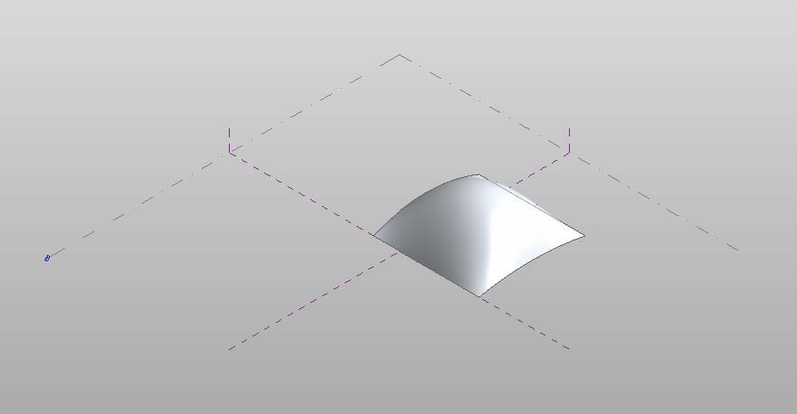
The following example moves the first profile curve of the given form by a specified offset. The corresponding figure shows the result of applying this code to the loft form from the previous example.
|
Code Region 14-5: Moving a profile |
public void MoveForm(Form form)
{
        int profileCount = form.ProfileCount;
        if (form.ProfileCount > 0)
        {
                int profileIndex = 0;   // modify the first form only
                if (form.CanManipulateProfile(profileIndex))
                {
                XYZ offset = new XYZ(-25, 0, 0);
                form.MoveProfile(profileIndex, offset);
                }
        }
}
|

Figure 58: Modified loft form
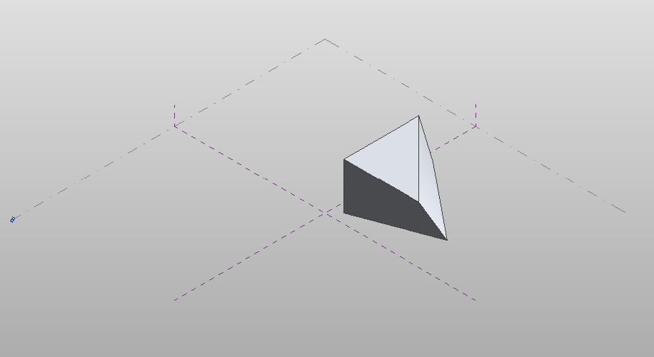
The next sample demonstrates how to move a single vertex of a given form. The corresponding figure demonstrate the effect of this code on the previous extrusion form example
|
Code Region 14-6: Moving a sub element |
public void MoveSubElement(Form form)
{
        if (form.ProfileCount > 0)
        {
                int profileIndex = 0;   // get first profile
                ReferenceArray ra = form.get_CurveLoopReferencesOnProfile(profileIndex, 0);
                foreach (Reference r in ra)
                {
                        ReferenceArray ra2 = form.GetControlPoints(r);
                        foreach (Reference r2 in ra2)
                        {
                                Point vertex = document.GetElement(r2).GetGeometryObjectFromReference(r2) as Point;

                                XYZ offset = new XYZ(0, 15, 0);
                                form.MoveSubElement(r2, offset);
                                break;  // just move the first point
                        }
                }
        }
}
|

Figure 59: Modified extrusion form