Learn how to manage the visibility and detail level of structural connections in your model.
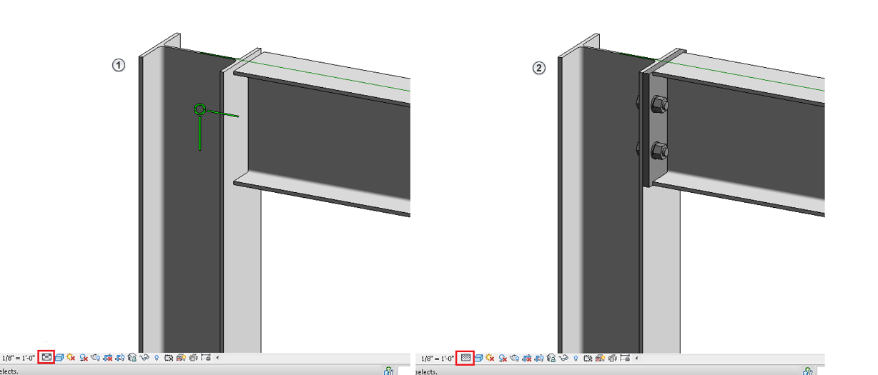
The display of steel connections adapts to different levels of detail. In
Medium level of detail
 , only the symbolic representation is displayed, while in the
Fine level of detail
 , the geometry of the structural connection is displayed.

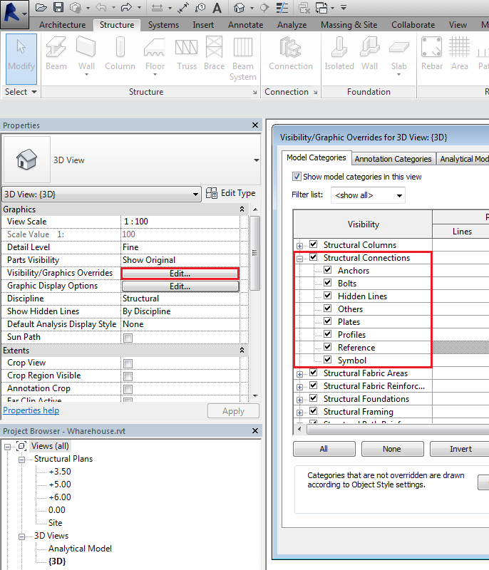
The visibility of steel connections, in a specific view, is controlled from the Visibility/Graphics Overrides menu. The connection elements are placed in the Structural Connections category and are split into six sub-categories: Anchors, Bolts, Plates, Profiles, Symbol and Others.

For the six defined sub-categories, you can only modify the Lines; the other parameters such as Pattern or Transparency, inherit the Structural Connection category settings.
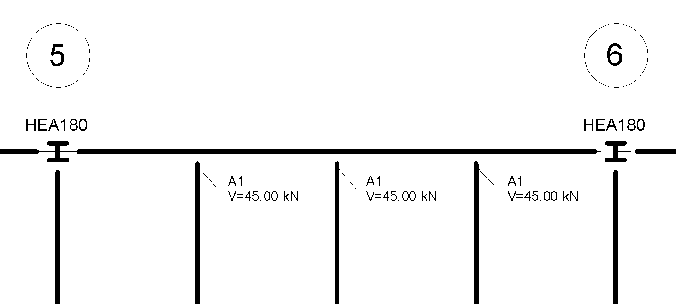
If the Reference subcategory box is not ticked, generic connections will be selectable but not visible in the view. This allows you to create connection tags in a view without visible symbols of the connections.
