We will now generate a solid mesh for the model.
- Select
 Mesh
Mesh  Mesh 3D Mesh Settings. The
Model Mesh Settings dialog box appears. Note that the default mesh type is
Solid.
Mesh 3D Mesh Settings. The
Model Mesh Settings dialog box appears. Note that the default mesh type is
Solid.
- Click the
Options button.
- Select Absolute mesh size from the Type drop-down list.
- Type 0.44 in the Size field.
- Click OK.
- Click Generate Mesh. The meshing process begins and is quickly completed.
- Click
No when asked about reviewing the mesh results. The meshed model appears as shown below. The second image shows the bolt zoomed-in and selected for better visibility.
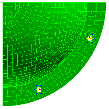
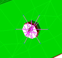
Notice how the bolts are connected to nodes on the CAD part surface mesh at each of the construction vertices.
- Click the
Options button.
- Click the
Home icon (
 ) that appears immediately above the ViewCube when the cursor is in that area. An isometric view of the completed model is displayed.
- To better see the mesh lines, click the
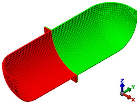
 View Appearance CAD Surfaces option to turn it off. Instead of using the original CAD surfaces, the model shading is now based on the FEA mesh. Typically, this shading method improves the mesh line rendering along curved surfaces and prevents mesh lines from being hidden by the surface shading. The model should appear as shown below.
- Click
 Save in the Quick Access Toolbar (QAT) to save your model.
Note: Even though the default mesh type is
Solid, only the surface mesh has been created at this point. By default, the generation of the interior mesh lines is postponed until the first time the
Run Simulation or
Check Model command is executed.
This tutorial is now complete. You can use the meshed model to complete the Bolted Flange Static Stress Analysis tutorial.