Since the cross-sectional area of the diagonal cross members is different from the horizontal and vertical members, they must be placed in a different part.
- Click
 View
View Navigate Orientation Front View.
 - Select
 Draw Draw Line.
 - Deactivate the Use as Construction check box.
- Type 2 in the Part: field.
- Starting at the lower-left corner, click the vertices alternating from left to right side. Move up the tower to create the diagonal members. The lines will snap to the nearest endpoint. In other words, the lines will not snap to the back side of the tower but to the side that is facing you. When you reach the top, the model should display as shown in the following image.
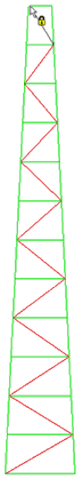
- Press Esc to terminate the current line.
- Click
 View Navigate Orientation Right View.
 - Starting at the lower-left corner, click the vertices alternating from left to right side. Move up the tower to create the diagonal cross members.
- Press Esc to terminate the current line.
- Click
 View Navigate Orientation Back View.
 - Starting at the lower-left corner, click the vertices alternating from left to right side. Move up the tower to create the diagonal cross members.
- Press Esc to terminate the current line.
- Click
 View Navigate Orientation Left View.
 - Starting at the lower- left corner, click the vertices alternating from left to right side. Move up the tower to create the diagonal cross members.
- Press Esc twice to exit the line command.
- Click
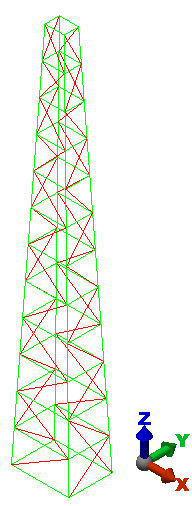
 View Navigate Orientation Isometric View.
 The tower should display as shown in the following image.
- Click
 Save on the Quick Access Toolbar (QAT) to save your model.
This tutorial is now complete. You can use this model to complete the Truss Tower Natural Frequency - Modal Analysis tutorial.