Now we define surface contact between the horizontal part and the vertical part.
- With the
 Selection
 Shape Point or Rectangle and
 Selection Select Surfaces commands active...
- Click and drag to draw a selection rectangle enclosing the surface where the horizontal and vertical parts meet, as shown in the following image. (Do not enclose the edges of the welds.)
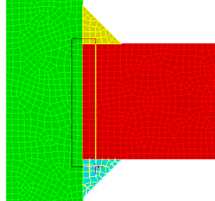 Note: Rectangle selection is necessary so that the surfaces of both parts are selected to define a contact pair. Also, on the previous page, you used the Select Related Vertices command. This action changed the selection mode from surfaces to vertices. That is why you had to change the selection mode back to surfaces for defining this contact pair.
- Click and drag to draw a selection rectangle enclosing the surface where the horizontal and vertical parts meet, as shown in the following image. (Do not enclose the edges of the welds.)
- Right-click in the display area and select
Contact Surface Contact. These two surfaces will not be able to penetrate each other but will freely slide or separate. The
Surface Contact
option ensures that tensile and shear loads are only carried by the welds.
- Press Enter to accept the default name for the contact pair.