Next, we create a mesh along the midplane of the model so we can analyze the part using plate elements.
- Click
 Mesh
Mesh  Mesh 3D Mesh Settings. The Model Mesh Settings dialog box displays.
- Select the Midplane option.
Note: This option collapses the original CAD part down to a set of single surfaces that are at the midplanes of the original solid members. After this is done, the thickness is no longer represented by the geometry and is instead specified via the plate element definitions. This is NOT to be confused with the Plate/Shell meshing option, which places plate elements on every surface of the original CAD model. For example, a Plate/Shell mesh of a solid rectangular prism would result in a hollow box with six plate element surfaces. A Midplane mesh of the same object would result in a single surface of plate elements with a defined thickness equal to the original CAD part thickness.
- Click the
Options button.
- Select Absolute mesh size from the Type drop-down list.
- Type 0.25 in the Size field.
- Click the OK button to accept the mesh options
- Click the Generate Mesh button. The meshing process starts.
- Select the Midplane option.
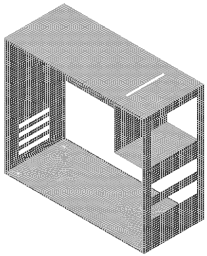
- When asked to review the mesh results, click
No. The meshed model displays as shown in the following image.
- Use the
 View Navigate Orbit Orbit,
 View Navigate Zoom Zoom, and/or
 View Navigate Pan commands to inspect the mesh in various areas of the model.
- Click
 Save on the Quick Access Toolbar (QAT) to save your model.
This tutorial is now complete. You can use the meshed model to complete the Computer Case Static Stress Analysis tutorial.