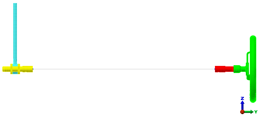
Next, use the Centroid Creator to locate the centroids at the ends of the crank and wheel stub shafts, to connect the end surfaces to the centroids, and to connect the two centroids with a beam element.
- Click
 View
View  Navigate Orientation Right View.
- With
 Selection Shape Point or Rectange and
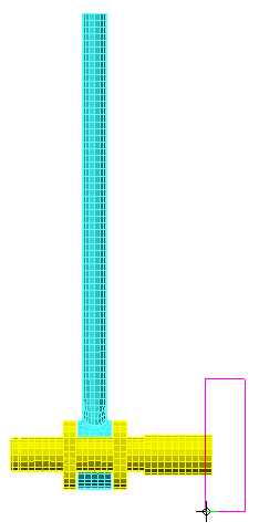
 Selection Select Surfaces active, click and drag the mouse to draw a selection window enclosing only the left edge of the hand wheel subassembly, as shown below:
- Click
 Draw Design Centroid Creator. The
Centroid Creator
dialog appears. Note that
Part 2 < Shaft Extension >, surface 14 < unnamed > is listed in the
Primary Centroid Geometry - Set 1
box. This is the surface that we selected just before clicking the
Centroid Creator
command.
Draw Design Centroid Creator. The
Centroid Creator
dialog appears. Note that
Part 2 < Shaft Extension >, surface 14 < unnamed > is listed in the
Primary Centroid Geometry - Set 1
box. This is the surface that we selected just before clicking the
Centroid Creator
command.
- Activate the option, Connect centroid to geometry with "spokes." The Part numbers have been set automatically to 5, the first available unused part number.
- Select Create centroids for two selection sets and connect them from the Centroid options drop-down menu.
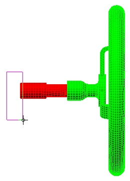
- Click and drag the mouse to draw a selection window enclosing only the right edge of the crank subassembly, as shown below:
- Click the Add button to the right of the Secondary Centroid Geometry - Set 2 box. Part 3 < Crank >, surface 5 < Unnamed > is listed in this box.
- Specify 6 in the Part field for the Secondary Spokes.
- Specify 7 in the Part field for the Connection Spoke.
- Click
OK. The model appears as shown in the following image: