Note:
The information in this section applies to linear and nonlinear structural analyses.
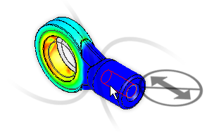
Apply surface pin constraints to cylindrical surfaces to prevent the surfaces from moving or deforming in combinations of radial, axial, or tangential directions.
- Select the appropriate surface
- Right-click in the graphics display and click Add.
- Select Surface Pin Constraint.
- In the Creating Pin Constraint Object dialog box, select the appropriate settings:
- Fix Radial: Restricts surfaces so they cannot move, rotate, or deform radially. Choose this setting to prevent penetration and separation.
- Fix Tangential: Restricts surfaces so they cannot rotate. Choose this setting to prevent the surfaces from moving tangentially around the circumference of the pin.
- Fix Axial: Restricts surfaces so they cannot move axially. Choose this setting to prevent the surface from moving along the length of the pin.
You can also add a description for the pin constraint.
- Click OK.
Caution: There is a know issue with the behavior of pin constraints. If you apply a pin constraint to a surface that intersects an adjacent part of an assembly, the surface may be over-constrained, producing incorrect analysis results. There are two workarounds to avoid this issue:
- Split the cylindrical surface in the CAD model so that the pin constraint surface does not extend all the way to the adjacent part. Then, reimport the CAD model and apply the pin constraint to the shortened cylindrical surface. The idea is to NOT allow a pin constraint surface to overlap any surface of a different part nor to share an edge with an adjacent part.
- Alternatively, define a cylindrical local coordinate system (LCS) and apply a General Constraint to the surface instead of a pin constraint. For a properly defined cylindrical LCS, the proper general constraints are as follows:
- Tx = Radial translation constraint
- Ty = Tangential translation constraint
- Tx = Axial translation constraint