This page discusses the results that are unique to the command,
Results Inquire Inquire Other Results Element Force and Moment. This command is applicable only to structural line elements (beam, truss, and pipe elements). The results are presented in a table.
Applicability: The
Other Results Element Force and Moment
command is available for all structural analysis types that produce stress results.
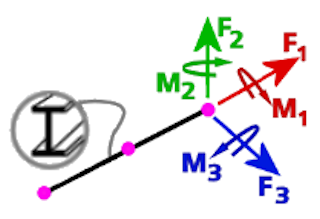
Figure 1: Element Force and Moment Directions
Element Force and Moment Results
While the X, Y, and Z coordinates are based on the global coordinate system, the element force and moment results are based on the element local coordinate system. The Local 1 axis corresponds to the axis of the line element (with the results listed as Axial Force and Axial Moment ). The Local 2 axis is at right angles to the Local 1 axis and lies in the plane defined by the two endpoints of an element (I- and J-nodes) and the Element Normal Point (K-node). The Local 3 axis is the cross-product of the Local 1 and Local 2 axes (following the right hand rule). For more information, refer to the Beam Element Orientation section on the Linear Analyses: Beam Elements page or the Nonlinear Analyses: Beam Elements page.
- All results are based on the current display units. The maximum (Max) and minimum (Min) values from each of the force and moment columns are listed in the bottom two rows of the table, respectively.
- Smoothing Options (specified in the
Results Contours Settings
panel) have no effect on the
Element Force and Moment
results.
The following data columns are included in the table of Element Force and Moment results:
Part Number and Element Number columns: A single node may be shared by more than one element and more than one part. A node has a unique set of force and moment results for each element that shares it. Therefore, the Part Number and Element Number are given for each row of the table to properly identify the result location.
Axial Force: This result is the force in the axial direction of the element. Positive values represent tension and negative values represent compression of the element.
Local 2 Force: This result is the shear force in the Local 2 axis direction.
Local 3 Force: This result is the shear force in the Local 3 axis direction.
Axial Moment: This result is the moment about the Local 1 axis (axial direction) of the element.
Local 2 Moment: This result is the bending moment about the Local 2 axis.
Local 3: Moment: This result is the bending moment about the Local 3 axis.
Note: The sign of the each moment follows the right hand rule. As viewed from the + end of an axis:
- Positive sign: Counter-clockwise moment
- Negative sign: Clockwise moment