For Static Stress with Nonlinear Material Models analyses, a Nastran tab appears within the Analysis Parameters dialog. This tab contains Nastran nonlinear solution processor parameters. These parameters are only applicable to models solved using the Nastran processor. They have no affect on the SimMech solver.
Note: The implementations of the Nastran parameters within Autodesk Simulation Mechanical do not necessarily support all of the input options that are available within the Autodesk Nastran Editor or the Autodesk Nastran In-CAD product. A subset of the available Nastran parameter options may be provided.
List of Parameters
- CONTACTSTAB
- Type: AUTO / Real (floating-point number)
- Default: AUTO
- Description: Surface contact solution stabilization option.
- The default setting, AUTO, automatically detects and stabilizes all surface contact in the model with a significant initial gap (that is, a gap ≥ model reference dimension * 1.0E-04). To control the stabilization stiffness, you can specify a scale factor, which multiplies the stabilization stiffness that is calculated automatically.
- LGDISP
- Type: ON / OFF
- Default: ON
- Description: Controls the use of large displacement and follower force effects and differential stiffness.
- For the default setting, ON, large displacement and follower force effects and differential stiffness are included. If LGDISP is set to OFF, large displacement and follower force effects and differential stiffness are not included.
- NLAYERS
- Type: Integer > 1
- Default: 10
- Description: Specifies the number of nonlinear material layers in quad and tri elements.
- A larger value of NLAYERS provides greater accuracy at the cost of computing time and storage requirements.
- NLCOMPPLYFAIL
- Type: ON/OFF
- Default: OFF
- Description: Nonlinear composite Progressive Ply Failure Analysis (PPFA) option.
- When set to the default, OFF, PPFA is not performed. When set to ON, composite plies that fail the user specified failure theory (FT field on the PCOMP Bulk Data entry) aree reduced in material stiffness based on reduction scale factors specified on MAT1 and MAT8 Bulk Data entries.
- NLINDATABASE
- Type: DELETE / STORE / UPDATE
- Default: DELETE
- Description: Controls the storage and retrieval of nonlinear data (such as loads, displacements, stress, and strain).
- The default value, DELETE, purges all nonlinear data when the program terminates normally. When set to STORE, the nonlinear database is stored in a single file with the same base name as the Model Results Output File, plus an increment, a load scale factor designator, and a .TDB file extension. When set to UPDATE, the nonlinear database is retrieved and stored.
- NLTOQUAD
- Type: ON / OFF
- Default: ON
- Description: Controls tension-only quad element support.
- When set to OFF, tension-only quad element support is disabled regardless of PSHELL Bulk Data entry settings and solution type.
- SLINEKSFACT
- Type: AUTO / Real (floating-point number)
- Default: AUTO
- Description: Specifies the initial penalty values used in slide line and surface contact analyses.
- Initial penalty values are calculated using: k * SFACT * | SLINEKSFACT |, where k is a value selected for each slave node based on the diagonal stiffness matrix coefficients. SFACT is specified in the SFACT field of the BCONP and BSCONP Bulk Data entries. The SLINEKSFACT value applies to all contact regions in the model. The default setting, AUTO, automatically adjusts model penalty values when convergence problems occur.
- SLINEMAXPENDIST
- Type: AUTO / Real (floating-point number) > 0.0
- Default: AUTO
- Description: Specifies the maximum slide line and surface contact element penetration distance.
- The primary purpose of this parameter is to prevent contact segments from unintentionally becoming active when the geometry is complex and large changes in configuration take place. The default setting, AUTO, uses the maximum contact surface or slide line reference length.
- SLINEMAXACTDIST
- Type: Real (floating-point number) > 0.0
- Default: 1.0E+30
- Description: Specifies the maximum slide line and surface contact element activation distance.
- The primary purpose of this parameter is to prevent unnecessary generation of contact segments when little or no movement is expected.
- The defaults setting, 1.0E+30, generates contact that allows unlimited movement. A small setting restricts contact generation to adjacent elements and is recommended for optimal performance when little or no movement is expected (such as with bolted connections). Note that a zero value should only be used if all master and slave nodes are collocated.
- SLINEOFFSETTOL
- Type: AUTO / Real (floating-point number)
- Default: AUTO
- Description: Specifies the tolerance for automatically converting surface weld elements to offset weld elements.
- Welded contact with an initial separation less than SLINEOFFSETTOL is converted to offset welded contact. The default setting, AUTO, is based on the model reference dimension multiplied by 1.0E-03. Note that specified values is an actual distance and is not normalized. For some models (that is, very large, very small, or with large gaps) the default SLINEOFFSETTOL value may not be well suited. Therefore, it is recommended that the analyst define this value explicitly. Note that for Automated Surface Contact Generation (ASCG), when a CONTACTGENERATE Case Control command is specified with the MAXAD field, SLINEOFFSETTOL is set to MAXAD.
- SLINESLIDETYPE
- Type: DYNAMIC / STATIC / AUTO / DISABLE
- Default: DYNAMIC
- Description: Contact penalty stiffness update method.
- When set to the default, DYNAMIC, the proximity stiffness-based update method is selected. When set to STATIC, the displacement-based stiffness update method is selected. For either setting the normalized SLINEMAXDISPTOL parameter defines the default TMAX value (maximum allowable penetration).
- SLINESTABKSFACT
- Type: Real (floating-point number)
- Default: 0.0
- Description: Used to stabilize surface contact in nonlinear static solutions.
- When set to a value greater than zero, a normal and in-plane stabilization stiffness is added between contact surfaces. The default value, 0.0, disables this feature. A value of 1.0 adds a stiffness approximately equal to the closed gap stiffness value. The stabilization stiffness is decreased with each full increment in each subcase using
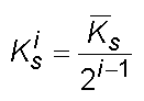
- where
 is the initial stabilization stiffness base on the specified SLINESTABKSFACT value, and
 is the stabilization stiffness for the current increment i.