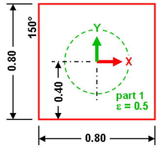
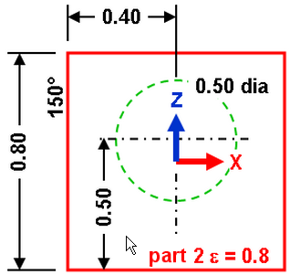
Problem Statement: A 0.5-m diameter hollow ball is inside a 0.8-m cubic box operating in a near vacuum as shown in the following figure. One side of the box is maintained at 150°C. The ambient temperature is -80°C. The conductivity for both objects is 3 W/(m°C). The thickness of the walls of the ball and the box is 0.001m. The ball has an emissivity of 0.5. The box has an emissivity of 0.8.
|
|
| Figure 1: Ball in a Box in the XY view and XZ view |
Find: Temperature of the ball.
This example only covers creating the model. For instructions on setting up and performing the analysis, see Ball in a Box with Body to Body Radiation.
Because the parts are thin, we use plate elements. First, we mesh the ball. There are many ways to do it, such as:
- Draw a circle with a specified number of divisions to create lines. Revolve the lines.
- Draw one construction circle, divide it into two construction arcs, and use the Divide One Object command to get a mesh around the semi-circle. Then revolve the mesh.
- Create a sketch and draw one semi-circle. Create a mesh on the arc and revolve it.
The first option is the fastest. But the second and third options provide the advantage of being able to adjust the mesh density and have the model update. Use the second option. Then the box is added with a series of 4-point meshes. Assume that the box is centered around the origin.
- Start a new FEA model (

 New) and
 - Set the analysis type to Thermal: Steady-State Heat Transfer.
- Set the unit system to be consistent with the problem statement. Click the Override Default Units button and set the Unit System drop-down to Metric mks (SI). Click the OK button to set the units.
- Click the New button and enter a model name.
- Add a circle for the ball using Draw Draw Circle Center and Radius. Make sure the Part number is set to 1 and that Use as Construction is checked. Enter (0,0,0.1) as the center, (0,0.25,0.1) as a point on the radius, and (1,0,0.1) as a point to define the plane containing the circle. Click Apply to finish the circle.
- Click the X button to close the Define a Circle dialog.
- To see the model more clearly, change the view to the top with View Navigate Orientation Top View.
- Select the circle and divide it. Selection Shape Point or Rectangle and Selection Select Construction Objects. Click the circle and then click Draw Modify Divide. Make sure that the number of divisions is set to 2, and then click OK. The circle is split into two arcs.
- Mesh one arc with seven divisions. Use the Mesh Structured Mesh Divide 1 Object command. Set the number of divisions AA' to 7. Click the arcs and then click Apply. The mesh lines appear superimposed on top of the construction arc, and a mesh entry is added to the Meshes branch of the tree view. The second arc is not being used.
- Click the X button to close the Object Mesh Setup dialog box.
- The mesh revolves to create the complete mesh of the ball. Click the Divide One Object Mesh entry in the Meshes branch of the tree view. All the mesh lines associated with the mesh are highlighted. Right-click the entry and choose Rotate or Copy. Activate the Copy check box. Type 14 in the Copy field and activate the Join check box. Type 360 in the Total angle field and select the DX radio button for the rotation axis. Set the rotation center point by clicking the Select Center Point button, and then click the construction vertex located at the center of the circle. Click OK. You now have the sphere.
- To create the box, use a series of 4-point rectangular meshes. Select Mesh Structured Mesh 4 Point Rectangular. Type 2 in the Part: field to place the mesh in a new part. To create the top of the box, define (-0.4, -0.4, 0.4) as Point A (-0.4, 0.4, 0.4) as Point B (0.4, 0.4, 0.4) as Point C and (0.4, -0.4, 0.4) as Point D. Type 7 in the AB: and BC: fields. Click Apply.
- Click the X button to close the Point Mesh Setup dialog.
- Copy the top of the box to the bottom. Select the 4-Point Mesh entry in the Meshes branch. Right-click it and choose Move or Copy. Activate the Copy check box, type 1 in the Copy field and deactivate the Join check box. Type 0.8 in the Total distance field, select the DZ radio button and click the Reverse direction button. Click OK to make the copy.
- To make the other four sides of the box easier, change the orientation to an isometric view: View Navigate Orientation Isometric View. Perhaps the ball will get in the way of creating the other meshes, so right-click Part 1 in the tree view and clear Visibility. By coincidence, the corner of the top appears to touch the corner of the bottom face. So, use View Navigate Orbit Orbit and rotate the model slightly so that each of the eight corners are clearly visible.
- Create the remaining four sides of the box using Mesh Structured Mesh 4 Point Rectangular. Make sure the number of divisions AB and BC is 7 each. Start with the three sides of the box: the front, back, and right side (the three sides with no load). Be sure to put these three sides on Surface 1. For each face, click the appropriate corners and click the Apply button to generate the mesh. Finish with the left side of the box (on the -X side of the model) and click each of the four corners. Since this face will have a load (150 degrees), place it on a different surface number: set Surface to 2. Click Apply to create the mesh. Tip: This process of meshing the left face last results in the perimeter of the left face on surface 1 and the interior lines on surface 2. It is a result of the mesher not creating duplicate lines at the junction with the other faces (which were created first). In this situation, it is good! Since a surface load is applied to the entire plate element if any lines are on surface 2, meshing the left face before any of the other faces would have created lines along the junction with the other faces on surface 2. Those elements would have incorrectly received the load that will be applied to surface 2. Naturally, that mistake could be corrected by selecting the lines on the perimeter of the left face and modifying the surface number to 1.
- Click the X button to close the Point Mesh Setup dialog box.
- Display the ball by right-clicking on Part 1 in the tree view and choose Visibility.