X: Strong axis
Y: Weak axis
Z: Primary axis
| Variable | Description |
|---|---|
| α | Rotation angle for principal axes of angle section |
| A | Cross-sectional area |
| Af | Area of compression flange |
| As | Shear area for tubular member - pipe |
| Asx | X shear area of prismatic member |
| Asy | Y shear area of prismatic member |
| b | Width of member (b ≤ d) |
| b0 |
Distance from neutral axis to edge of web:
|
| be | Effective width of structural tubing member |
| bf | Width of flange |
| Cb | Bending coefficient dependent upon moment gradient (section F) |
| Cc | Column slenderness ratio separating elastic and inelastic buckling (section E) |
| Cmx, Cmx | Coefficient applied to bending term in interaction equation (section H) |
| d | Depth of member (d ≥ b) |
| E | Modulus of elasticity |
| E0 |
Distance of the shear center from center line of web for channel: E0 = e0 + tw / 2 |
| Fa | Maximum allowable compressive stress |
| Fb | Maximum allowable bending stress |
| Fbx | Maximum allowable strong axis bending stress |
| Fby | Maximum allowable weak axis bending stress |
| Fex, Fey | Euler stress for a prismatic member divided by factor of safety |
| Ft | Maximum allowable tensile stress |
| Fy | Yield stress |
| Fn | Maximum allowable shear stress |
| fa | Computed axial stress (either tension or compression, both taken as positive) |
| fb | Computed bending stress (taken as a positive quantity) |
| fbx | Computed strong axis bending stress |
| fby | Computed weak axis bending stress |
| fvx | Computed shear stress in X direction |
| fvy | Computed shear stress in Y direction |
| h |
Clear distance between flanges in I-shaped members: h = d 2tf |
| Ix, Iy | Moments of inertia about principal axes |
| Iu, Iv | ments of inertia about principal axes of angle section member |
| K | ective length factor for prismatic member |
| L | Distance between cross sections braced against twist or lateral displacement of the compression flange |
| Lb | Laterally unsupported length of the compression flange. |
| Lc | Maximum unbraced length of the compression flange. |
| Lx, Ly | L in X and Y directions |
| M1, M2 | Smaller and larger moment at end of unbraced length, respectively. |
| P | Axial force load |
| r | Governing radius of gyration |
| rT | Radius of gyration of a section comprising the compression flange plus 1/3 of the compression web area, taken about an axis in the plane of the web |
| rx, ry | Radius of gyration about principal axes |
| t | Thickness |
| tf | Thickness of flange |
| U, V | Principal axes of angle section member |
| u, v | Distances from principal axes |
| x, y | Offsets of centroid of angle section |
Allowable Stresses
X is the strong axis, and Y is the weak axis for all I-shaped and members and channels. Tees can have either axis as their strong axis.
1. Strong Axis Bending Stress
- Members loaded along their weak axis, Y (bent about their strong axis, X).
- This maximum allowable strong axis bending stress is referred to as Fb in this section.
- Two categories are considered:
- I-shaped members, tees and channels
- Pipes and structural tubing, including square and rectangular ducts and pipes
1.A. Members with compact sections
- Includes tees with compact flanges.
- Tees loaded along then X-axis are not considered, in this code check.
- Applicable to all I-shaped and members and channels, and tees with Ixx > Iyy. Tees with Ixx ≤ Iyy are not considered in code check.
Category I. I-shaped members, tees and channels Section F1.1
The allowable bending stress is
| Fb = 0.66 Fy | (F1-1) |
with the constraint that Lb ≤ Lc, which is given by the smaller of:

|
(F1-2) |
-
Fb = 0.66 Fy (F3-1) - subject to the following conditions:
- Rectangular members cannot have a depth greater than 6 times the width.
- Lb ≤ Lc, where Lc is given by

(F3-2)
Category II. Pipes and structural tubing Section F3.1
The allowable bending stress is
except, that Lc need not be less than 1200 (b/Fy), M1 is the smaller and M2 is the largest bending moments about the ends of the unbraced length, taken about the strong axis.
1.B. Members with noncompact sections
- Must satisfy constraint, Lb ≤ Lc (F1-2) or (F3-2), including that rectangular members cannot have a depth greater than 6 times the width.
- Includes tees with noncompact flanges.
- Tees loaded along the X-axis are not considered.
Category I. I-shaped members, tees and channels Section F1.2

|
(F1-3) |
Category II. Pipes and structural tubing Section F3.2
| Fb = 0.60 Fy | (F3-3) |
1.C. Members with compact or noncompact sections with Lb > Lc
- The section is only applicable to Category I. I-shaped members, tees and channels.
If member is in tension,
| Fb = 0.60 Fy | (F1-5) |
If member is in compression, the allowable bending stress is determined as the larger value from equations (F1-6) or (F1-7) and (F1-8), with the exceptions:
- Only equation (F1-8) is used for channels.
- None of these equations apply to tees in compression, thus such tees are not considered.
When

|
(F1-6) |
When 

|
(F1-7) |
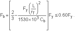
For any value of L/rT:

|
(F1-8) |
Cb is conservatively taken as unity (1.0) in equations (F1-6), (F1-7) and (F1-8).
2. Weak Axis Bending Stress
- The section is only applicable to Category I. I-shaped members, tees, channels and solid bars (prismatic members).
- Category II. Structural tubing in this category use same value of Fb found for their strong axis for their weak axis.
- Members loaded along their strong axis, X (bent about their weak axis, Y).
- This weak allowable strong axis bending stress is referred to as Fby, yet in this section it is labeled as Fb.
- Applicable to all I-shaped members; all others are not considered.
-
Fb = 0.75 Fy (F2-1)
2.A. Members with compact sections: Section F2.1
-

(F2-3)
2.B. Members with noncompact sections: Section F2.2
3. Tensile Stress
| Ft = 0.60 Fy | Section D1 |
4. Compressive Stress
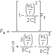
Section E2
![]()

|
(E2-1) |
where KL/r is the largest of KLx / rx and KLy / ry, which are equal for pipes and squares, and 
![]()

|
(E2-2) |
5. Combined Stress
Chapter H
5.A. Axial compression and bending
The following requirements must be satisfied for members experiencing both axial compression and bending:

|
(H1-1) |

|
(H1-2) |
When fa / Fa ≤ 0.15, Equation (H1-3) is used in lieu of Equations (H1-1) and (H1-2).

|
(H1-3) |
The coefficients, also known as the Euler stress divided by safety factor, Fex and Fey are given by the following:

The coefficients Cmx and Cmy have a default value of 0.85.
5.B. Axial tension and bending
The following requirements must be satisfied for members experiencing both axial tension and bending:

|
(H2-1) |