This page is applicable to the following three commands listed in the
Results Inquire Inquire Other Results drop-down menu:
- Reaction Force and Moment
- Internal Force and Moment
- Applied Force and Moment
Features Common to the Reaction, Internal, and Applied Force and Moment Results
Smoothing Options
(specified in the
Results Contours Settings
panel) have no effect on the
Reaction, Internal, or
Applied Force and Moment
results. Enabling or disabling the
Smooth Results
mode also has no effect on the results for these three tables.
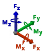
Figure 1: Force and Moment Directions
Reaction Force and Moment Results
Applicability: The
Other Results Reaction Force and Moment
command is available for the following four analysis types:
- Static Stress with Linear Material Models
- MES with Nonlinear Material Models
- Static Stress with Nonlinear Material Models
- Riks Buckling Analysis (MES Riks)
The following data columns are included in the table of Reaction Force and Moment results:
Reaction Force X, Reaction Force Y, and Reaction Force Z: These three columns list the X, Y, and Z components, respectively, of the reaction force at each specified node. The results are shown using the current display units. The maximum (Max), minimum (Min), and Sum of the listed reaction forces are reported in the bottom three rows of the table, respectively.
Reaction Moment X, Reaction Moment Y, and Reaction Moment Z: These three columns list the X, Y, and Z components, respectively, of the reaction moment at each specified node. The results are shown using the current display units. The maximum (Max), minimum (Min), and Sum of the listed reaction moments are reported in the bottom three rows of the table, respectively. Reaction moments are applicable to elements that have rotational degrees of freedom (such as beam, plate, and shell elements). Solid and 2D elements do not support rotational degrees of freedom and produce zero nodal moment results.
Note:
- The sign of each result represents the direction of forces and moments exerted by the model against the supports. The results are not the equal and opposite reactions exerted by the supports against the model.
- Reaction forces and moments are non-zero only where the model is constrained. Values are zero at unconstrained nodes. However, very small, near-zero numbers (such as 4.5 x 10‑13) are often reported at unconstrained nodes due to the numerical solution method.
Internal Force and Moment Results
Applicability: The
Other Results Internal Force and Moment
command is available only for the following analysis type:
- Static Stress with Linear Material Models
The following data columns are included in the table of Internal Force and Moment results:
Internal Force X, Internal Force Y, and Internal Force Z: These three columns list the X, Y, and Z components, respectively, of the internal force at each specified node. The results are shown using the current display units. The maximum (Max), minimum (Min), and Sum of the listed internal forces are reported in the bottom three rows of the table, respectively.
Internal Moment X, Internal Moment Y, and Internal Moment Z: These three columns list the X, Y, and Z components, respectively, of the internal moment at each specified node. The results are shown using the current display units. The maximum (Max), minimum (Min), and Sum of the listed internal moments are reported in the bottom three rows of the table, respectively. Internal moments are only applicable to elements that have rotational degrees of freedom (such as beam, plate, and shell elements). Solid and 2D elements do not support rotational degrees of freedom and produce zero nodal moment results.
Note:
- In most cases, internal forces and moments are non-zero only where the model is constrained. However, very small, near-zero numbers (such as 4.5 x 10‑13) are often reported at unconstrained nodes due to the numerical solution method.
- When thermal strain is present (either expansion or contraction) non-zero internal force and moment results are calculated at all nodes (not just the constrained ones).
Applied Force and Moment Results
Applicability: The
Other Results Applied Force and Moment
command is available only for the following analysis type:
- Static Stress with Linear Material Models
The following data columns are included in the table of Applied Force and Moment results:
Applied Force X, Applied Force Y, and Applied Force Z: These three columns list the X, Y, and Z components, respectively, of the applied force at each specified node. The results are shown using the current display units. The maximum (Max), minimum (Min), and Sum of the listed applied forces are reported in the bottom three rows of the table, respectively.
Applied Moment X, Applied Moment Y, and Applied Moment Z: These three columns list the X, Y, and Z components, respectively, of the applied moment at each specified node. The results are shown using the current display units. The maximum (Max), minimum (Min), and Sum of the listed applied moments are reported in the bottom three rows of the table, respectively. Applied moments are only applicable to elements that have rotational degrees of freedom (such as beam, rigid, and shell elements). Solid and 2D elements do not support rotational degrees of freedom and produce zero nodal moment results.
Note:
- In most cases, applied forces and moments are non-zero only where a structural load has been applied.
- When thermal strain is present (either expansion or contraction) non-zero internal force and moment results are calculated and listed as applied loads at all nodes (not just the ones to which you applied structural loads).