To insert profiles, the drawing file must have Civil 3D settings defined.
To insert profiles
- Open a Utility Design template.
- Use the INSERT command to insert a Civil template.
Here is an alternative workflow.
- Open a Civil template in Utility Design.
- Use the AUDINDUSTRYMODELADD command to add the Utility Design industry model.
To insert a profile in model space and paper space
- Click Home
 Annotation panelCreate Profile.
- Select the overhead segments for which to insert a profile.
- Specify additional alignment length.
- Specify the location of the profile.
A civil profile is created for the selected overhead design, including the poles connected with the segments.
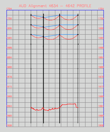
You can also create profile for underground lines and structures. Selecting an underground segment will add all directly contained ducts and conductors to the generated profile. The profile will show the extent of line 3D geometry projected to the profile. A line will be shown for both the upper and lower extent of the 3D geometry, based on the outer diameter of the line.
To configure styles for profiles
To configure the styles and settings for profiles, see Civil Options.
The profile style name settings for Wire, Pole, and Underground lines (Duct, Conductor, etc.) allow overriding via rule Text Expressions. If a Text Expression is defined for the corresponding feature class with a name matching the style name specified in the Civil settings, that rule will be used as the style name for the profile. If not specified, the style name in Civil settings will be used.