- The UV editor works only with NURBs data that has been tessellated in VRED. Any other mesh or previously tessellated data will not work.
- If the geometry is re-tessellated, its UV coordinates are not preserved, and changes to the UVs need to be redone.
Display UVs in the UV Editor
- Choose .
- In the UV Editor, choose
Select Objects as the
Selection Mode.
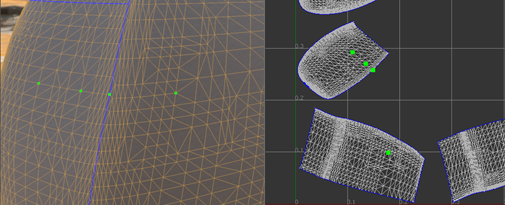
In Select Objects mode, only nodes in the scene can be selected in the scene view and nothing can be selected in the UV Editor view.
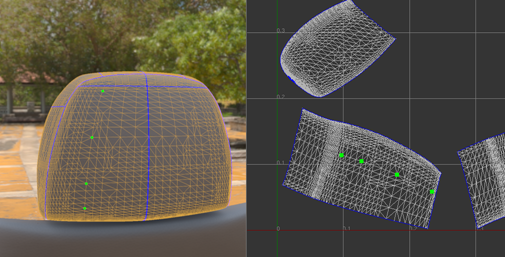
- In the scene view, select the geometry nodes. The UVs for the selected nodes are displayed in the UV Editor.
Alternatively, select the nodes in the scene view and then choose to open the UV Editor with the UVs for the selected nodes displayed.
Navigate the View in the UV Editor
- To pan, hold down the middle mouse button and drag.
- To zoom, hold down the right mouse button and drag.
- To refocus the view, press the F key on your keyboard.
- If no island/edge/vertex is selected, the view zooms to display all UV coordinates of selected geometries.
- If some islands/edges/vertices are selected, the view focuses only on the UV coordinates of the selection.
Select Islands of Selected Geometry Nodes
- In the UV Editor, Shift+middle-click on the view and choose
Select Islands as the
Selection Mode.
(A UV island is a sub-part of the mesh where every vertex is directly or indirectly connected to every other vertex in the same island.)
- Use the standard VRED object selection methods to select the components
To Select Objects in Render View.
Tip: To select only those components on the front-most surfaces, or alternatively to select all components in the selection frame whether they are behind another surface or not, in the scene view, toggle .
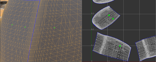
When you select an island, its corresponding sub-mesh is highlighted white in the UV Editor.
Selected islands display in the scene view only when OpenGL wireframe rendering is selected (), not when using raytracing.
To see the borders, select the Show Borders option in the Visualize section of the UV Editor.
Select Edges of Selected Geometry Nodes
- In the UV Editor, Shift+middle-click on the view and choose Select Edges as the Selection Mode.
- Use the standard VRED object selection methods to select the components
To Select Objects in Render View.
Tip: To select only those components on the front-most surfaces, or alternatively to select all components in the selection frame whether they are behind another surface or not, in the scene view, toggle .
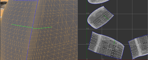
Hold the Shift or Shift+Ctrl keys and hover the cursor over an edge to highlight it. The edge highlights red if that edge has not been selected or yellow if it has been selected already.
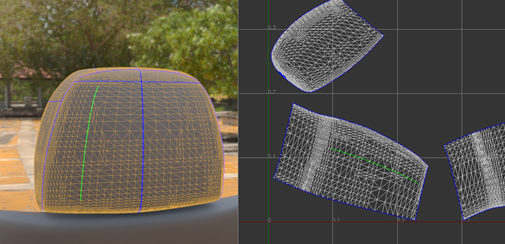
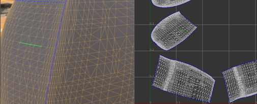
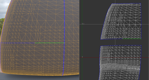
Selected edges are highlighted green in the UV Editor.
They display in the scene view only when OpenGL wireframe rendering is selected (), not when using raytracing.
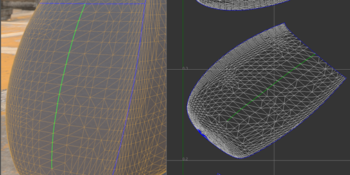
To select a chain of edges:
- Click Start Picking in the Selection Mode section of the UV Editor.
- Define the edge selection path by picking at least two points.
- When point picking is finished, click
End Picking.
The shortest path connecting each way point, in the order it was picked, is selected and added to the current edge selection.
If any way point is located on a different UV island, a path that connects all way points cannot be constructed.
Adding a way point on the border between two islands may guide the path to go across the border.
 Note: If there is any physical gap between two islands, it is impossible for a path to go across it.Tip: Turn on Show Border when constructing a path.
Select Vertices of Selected Geometry Nodes
- In the UV Editor, Shift+middle-click on the view and choose Select Vertices as the Selection Mode.
- Use the standard VRED object selection methods to select the components
To Select Objects in Render View.
Tip: To select only those components on the front-most surfaces, or alternatively to select all components in the selection frame whether they are behind another surface or not, in the scene view, toggle .
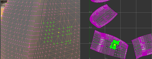
Select Show All Vertices to display all vertices in magenta in the UV Editor.
They display in the scene view only when OpenGL wireframe rendering is selected ), not when using raytracing.
Hold the Shift or Shift+Ctrl keys and hover the cursor over a vertex to highlight it. The vertex highlights red if it has not been selected or yellow if it has been selected already.
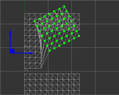
Selected vertices are highlighted green.
Cut and Sew Edges of a UV Mesh
Cut Edges
Cuts are important to the unfolding process. They allow the UV textures to unfold with as little distortion as possible. When unfolded, the UV mesh should lay flat without overlapping.
- In the UV Editor, choose
Select Edges mode and select two or more edges.
Tip: To highlight the borders, select Show Borders.
- In the
Selection Mode section, click
Cut Edges.
The mesh is cut along the selected edges.
The edges become new borders after the cut.
 Note: Cutting border edges has no effect.
Sew Edges
There are two ways to sew edges: sew along borders or sew neighboring islands.
Sew along Borders
- In the UV Editor, choose
Select Edges mode and select two border edges to sew together.
Tip: Select Only Select Borders when selecting borders using rectangle selection.
- In the
Selection Mode section, click
Sew Edges.
If sewing is successful, a border edge becomes a normal edge.
The UV coordinates of vertices on both sides of a border are averaged and used as the new coordinates for the sewed vertices.
Sew Neighboring Islands
This method has the same effect as selecting corresponding border edges and sewing them using Sew Edges. However, this method may be more efficient in some cases.
- In the UV Editor, choose
Select Islands mode and select one or more islands to sew together.
- In the
Selection Mode section, click
Sew Islands.
VRED attempts to sew neighboring islands together.
If the island has an internal border, which means the other side of the border belongs to the same island, it is also sewed. This may not be the desired behavior and can be changed by selecting the option Only Borders Between Islands, next to Sew Islands. When this option is selected, only borders between different islands can be sewed.
- Sewing along non-border edges has no effect.
- To sew the border, the physical locations, normal vectors, and other per-vertex attributes of vertices on both sides of a border must be the same. For example, a physical gap cannot be sewed by the sew tools.
- Only islands belonging to the same triangle mesh or the same shell can be sewed together.
Unfold a UV Mesh
UV coordinates can be created by unfolding a surface in 3D space onto a 2D plane. Each UV island is an isolated and detachable piece so it is the basic unit to perform unfolding.
The quality of unfolding depends on how easily each island can unwrap onto a plane. A relatively planar surface is usually easy to unfold and produces a good result. On the other hand, a surface wrapped with a lot of tension is tricky to unfold and usually incurs a lot of distortion. Experience and effort may be needed to cut and sew the surfaces before unfolding to achieve a satisfactory result.
Unfold All Geometries
- Select the geometries to unfold.
- In the
Unfold section of the UV Editor, click
Unfold All.
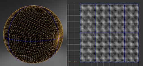
VRED attempts to pack the UV islands belonging to the same geometry into the unit UV space after unfolding.
Unfold Selected Islands
- In the UV Editor, choose
Select Islands mode and select one or more islands unfold.
- In the
Selection Mode section, click
Unfold Islands.
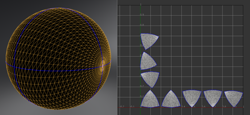
The new UV coordinates for the selected islands are scaled roughly as large as before unfolding and placed in their original position.
The Iterations field in the Unfold section It indicates the maximum computation allowed to perform the unfolding. It affects both Unfold All and Unfold Islands. The time spent on unfolding may be reduced by having less iterations, but the result may be worse.
Manipulate UVs
Use the options in the Manipulate section of the UV Editor to manipulate coordinates of selected islands/edges/vertices.
Flip UVs in U or V Direction
To flip the UV coordinates of selected islands/edges/vertices in either the U direction or V direction, click Flip in U Direction or Flip in V Direction, respectively.
Translate UVs
To translate the UV coordinates of selected islands/edges/vertices:
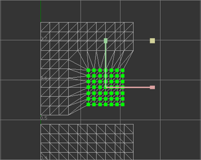
- Hold the Shift+W keys to toggle the display of the translation manipulator. The manipulator displays at the centroid position of the selection.
- Continue to hold the Shift key and hover over the manipulator to select one or both translation axes and highlight the corresponding arrow in yellow.
- Still holding the Shift key, drag to translate the selection.
Rotate UVs
To rotate the UV coordinates of selected islands/edges/vertices:
- Hold the Shift+E keys to toggle the display of the rotation manipulator. The manipulator displays at the rotation pivot position of the selection.
- Continue to hold the Shift key and hover over the manipulator to select the rotation tool and highlight the manipulator in yellow.
- Still holding the Shift key, drag to rotate the selection.
- To move the position of the rotation pivot, hold the Shift+Q key to display a manipulator with two blue arrows. Drag to reposition the pivot.
Scale UVs
To scale the UV coordinates of selected islands/edges/vertices:
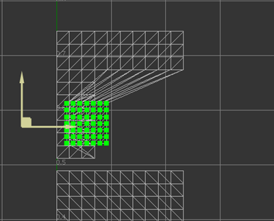
- Hold the Shift+R keys to toggle the display of the scaling manipulator. The manipulator displays at the scale pivot position of the selection.
- Continue to hold the Shift key and hover over the manipulator to select a scaling axis and highlight it in yellow if the cursor is near that axis, or select both axes if the cursor is near the square at the top right, highlight it in yellow.
- Still holding the Shift key, drag to scale the selection.
- To move the position of the scale pivot, hold the Shift+Q key to display a manipulator with two pale yellow arrows. Drag these arrows to reposition the pivot.
Modify Multiple UVs at Once Using Lattice Deformation
Modify the layout of multiple UVs at once using a 2D lattice deformer.
Create a Lattice
- Select the islands/edges/vertices you want to manipulate, and in the
Manipulate section of the UV Editor, select
Use UV Lattice. A lattice that is large enough to cover all the selected vertices is created.
or
- To start a new lattice, hold the Shift key and drag a rectangle in the UV Editor.
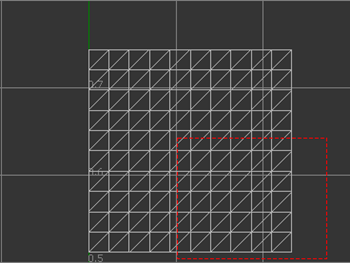
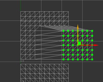
To toggle the automatic fitting of the rectangle you dragged to the bounding rectangle of the selected vertices, select Use Bounding Rectangle.
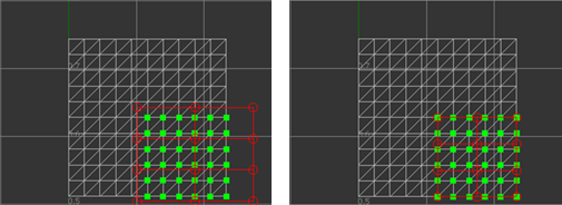
Left: Off, Right: On
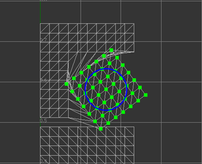
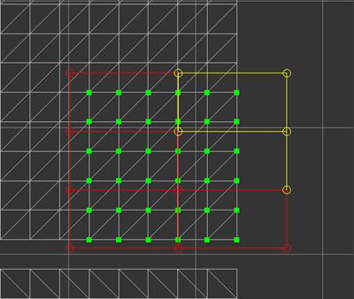
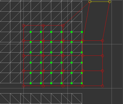
Circles represent the control points of the lattice. They are distributed evenly in rows and columns. You can select control points and the lines connecting them. Select and deselect them the same way you select islands/edges/vertices.
Selected control points are yellow. If the two points that connect a line are both selected, then that line is also yellow.
Deform UV Coordinates
Select lattice control points and drag.
Columns and Rows specify how many control points each row and column of the lattice has. The more columns and rows there are, the more local the influence of moving a control point.
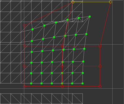
Falloff 1.0
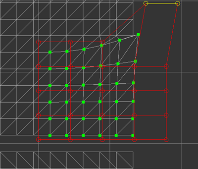
Falloff specifies how much influence the deformation should bring to the original UV coordinates. It is a value between 0.0 and 1.0. If 1.0 is used, UV coordinates are fully influenced by the deformation. If 0.0 is used, UV coordinates are not affected by the deformation at all. 1.0 was used in the previous example and 0.0 is used in the following example.
Falloff 0.0
Best Practices
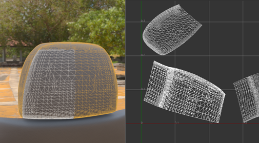
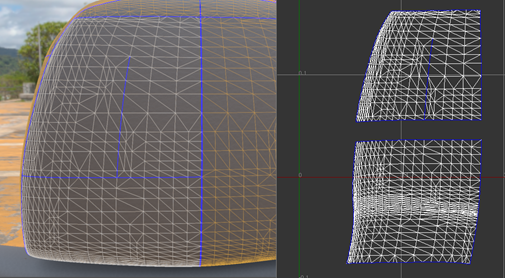
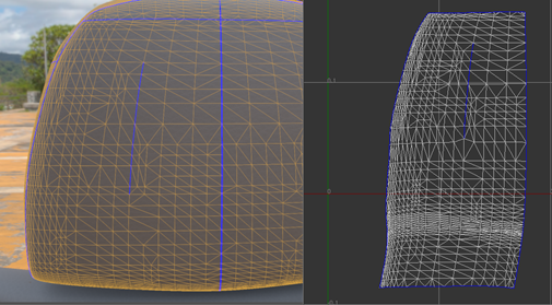
If a complex surface geometry comes in as a normal triangle mesh which is one large piece, UV islands need to be created by cutting the surface so that each of them can be unfolded. If the unfolding result looks strange or unbalanced, more cuts are likely needed in the surface.
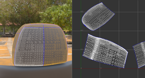
A shell node which may contain a number of NURBS components is considered as one geometry node and the UV coordinates of neighbor NURBS surfaces may be sewed together. If each NURBS surface is small and relatively planar, sewing UV islands of NURBS surfaces to form larger islands and then unfolding may be a more efficient way to work.
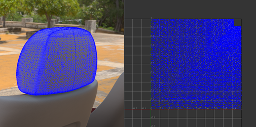
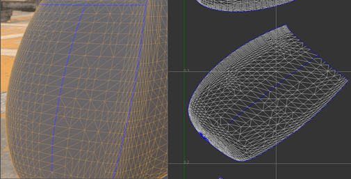
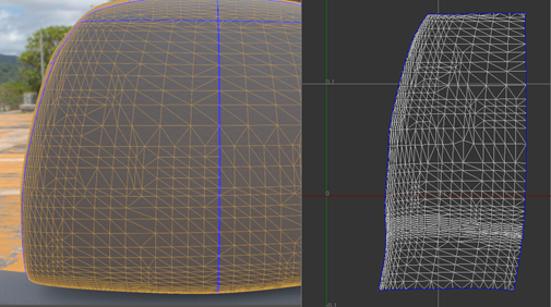
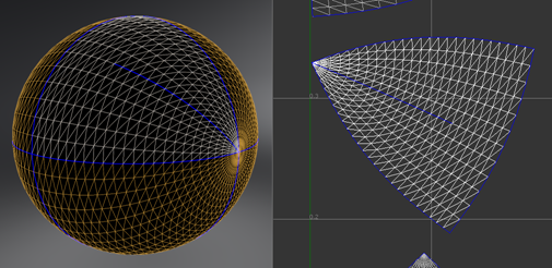
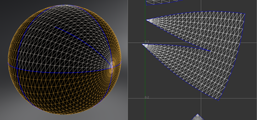
Sometimes the triangle mesh is completely split. This can be detected by enabling the border visualization and every edge will be drawn in blue. If unfolding is done on such geometry, a result like this will be returned.